
A single-fiber link stops working after one SFP is replaced. The replacement has the same speed, the same advertised distance and the same connector. The missing detail may be the direction of its wavelengths.
BiDi transceivers send and receive over one fiber by using a compatible wavelength arrangement. The transmitting wavelength at one end must be supported by the receiver at the other, and the reverse direction must also match. Ordering two units with the same directional specification can therefore produce an incompatible pair.
The most reliable purchasing record identifies both ends explicitly. Labels such as A/B, U/D or a colored latch can help within a product family, but they should not replace the actual transmit and receive specifications when comparing suppliers or managing spares.
Write the pair as two directional statements
For an illustrative pair, end A might transmit at 1310 nm and receive at 1550 nm. End B would need a compatible arrangement transmitting at 1550 nm and receiving at 1310 nm. The values in this example are not a universal BiDi standard or a TODAHIKA product specification.
Other products use other wavelength plans. Cisco's Gigabit SFP datasheet, for example, describes a complementary 1310/1490 nm arrangement for its 1000BASE-BX10 pair. The principle is complementary transmission and reception; the actual numbers come from the selected pair.
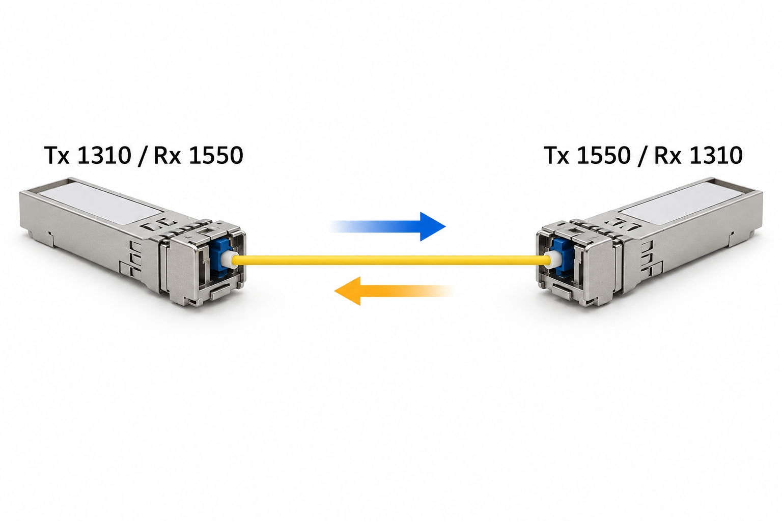
For each end, record the manufacturer's complete module code, supported data rate, Tx wavelength, Rx wavelength range and optical specifications. Include the host device and port. This gives the installer a clear mapping and prevents a warehouse label from becoming the only compatibility evidence.
A matching wavelength is necessary, but not sufficient
Check the optical interface and line rate as well as wavelength. Two modules that use similar wavelengths may be intended for different systems and may not interoperate. A matching metal form factor or a nominal wavelength does not establish protocol compatibility.
Then check the fiber, connectors and approved operating conditions. The route must satisfy the module's supported fiber and loss requirements. The host must support the selected module and speed, and the transceiver must be suitable for the environment where it is installed.
| Requirement | Record for end A and end B | Why it matters |
|---|---|---|
| Interface and rate | Exact optical interface and supported speed | Similar packaging does not establish interoperability |
| Wavelength direction | Tx and Rx specifications | Each transmitter must match the opposite receiver |
| Optical limits | Minimum/maximum Tx, sensitivity and maximum Rx | Both low-power and high-power cases must be acceptable |
| Fiber and connector | Fiber type, connector and polish requirements | Physical mating alone does not establish a correct channel |
| Host support | Switch or converter model, port and relevant revision | The module must operate in the selected host |
| Environment | Applicable temperature and installation limits | A compatible bench pair may still be unsuitable for the field cabinet |
If a supplier proposes a cross-brand pair, request written confirmation for those exact ordering codes and test the combination. Avoid replacing an explicit compatibility statement with the assumption that every module described as “BiDi 1G” is interchangeable.
Calculate the two directions independently
A single strand does not mean there is only one optical budget. Each transmitter, receiver and wavelength contributes to its own direction's calculation. The route's loss can differ with wavelength, and the modules' transmit and receive limits may differ as well.
Suppose, purely for illustration, one direction has 10 dB available before the project's allowance and the estimated path loss at its wavelength is 5 dB. The reverse direction has 8 dB available and an estimated loss of 4.5 dB. The remaining values are 5 dB and 3.5 dB respectively before applying the chosen design allowance. The weaker direction governs whether the pair meets that requirement.
Also check the high-power case using maximum launch and the lowest relevant path loss. A short test lead is not automatically suitable for every high-output pair. Follow the selected optics' instructions for any required attenuation and avoid confusing the maximum operating input with a damage specification.
The calculation should be retained alongside the pair record. It explains why a spare with the same wavelength and distance label may still need review if its transmit range or receiver limits differ.
Troubleshoot a replacement without changing every variable
Start by reading both module labels and comparing them with the accepted pair record. Confirm that the replacement is the correct directional member. Check that it is fully seated in the supported host port and that the intended port configuration is in place.
Next inspect the fiber path and connector condition using appropriate tools. Follow an inspect, clean if needed, and reinspect process. Fluke Networks' fiber troubleshooting reference explains how different path faults can produce loss. Do not use direct visual inspection of a live optical aperture as a test.
Where supported, compare receive-power readings at both ends. A one-sided observation can be particularly useful: one direction may have optical power while the other does not. Interpret those readings against the actual module limits, and use an appropriate test method if the operating diagnostics do not provide enough evidence.
After restoring the optical link, verify useful traffic in both directions. A link indicator alone does not prove the required VLAN path, application service or sustained error-free operation under the accepted workload.
Organize spares by role as well as by family
For a site with many identical links, maintain a spare record that distinguishes the two directional members. Identify the role in a way that remains meaningful when hardware is moved: building A side and building B side, or the corresponding documented uplink endpoints.
Do not rely only on latch color. Colors can vary across suppliers and product lines, and they are easy to misread in a crowded cabinet. Keep the complete ordering code and Tx/Rx mapping on the spare label or accompanying inventory record.
A compatible pair supplied together can simplify initial deployment, but future replacement still needs the individual mapping. Retain both module identities after installation. Otherwise a technician may know which pair was purchased without knowing which member belongs at the failed end.
Put pair confirmation into the quotation
For a TODAHIKA fiber media converter or SFP-based switch inquiry, provide the host models, single-fiber route, required speed, measured or estimated loss and cabinet conditions. Ask for a two-line module schedule showing the exact device at each end.
Require any alternative to be assessed against the same schedule, including its optical limits and environmental rating. The lowest-priced individual module is not necessarily a usable spare for the installed pair.
At acceptance, retain the pair labels, port assignment, relevant settings, installed-path test and operating baseline. That small amount of documentation turns a future replacement from a trial-and-error exercise into a controlled substitution with clear compatibility evidence.
Post time: Oct-06-2026


