
A camera answers ping, its uptime keeps increasing, and the switch reports stable PoE. Yet the operator sees frozen frames when several cameras are displayed together. That combination moves the investigation beyond basic power and reachability.
Ping generates relatively little traffic. A successful reply does not demonstrate that a link can carry the required video streams, that the recorder can ingest them or that the viewing workstation can decode them. The useful starting point is the route taken by the missing video and the first place where evidence changes.
For an integrator, this investigation also provides the information needed to specify the next switch correctly. Count traffic through each link, in each direction, at the operating state that causes the complaint.
Draw the recording and viewing paths separately
Mark the cameras, access switches, aggregation switches, recorder and viewing clients. Add the actual negotiated speed of each link. A port capable of Gigabit operation may currently be connected at 100 Mb/s because of the device, cabling or configuration.
Then identify where a stream originates. A viewing client may request video from the recorder or directly from the camera. Those arrangements place different loads on the camera uplink. Playback from a central recorder may travel through a different path from incoming recordings. Do not add every visible stream to every link simply because it belongs to the same surveillance system.
For unicast traffic, separate sessions can consume additional capacity on the links they traverse. Multicast has a different distribution model and needs appropriate network support. Confirm the actual application behavior before assuming that multiple viewers share one network copy.
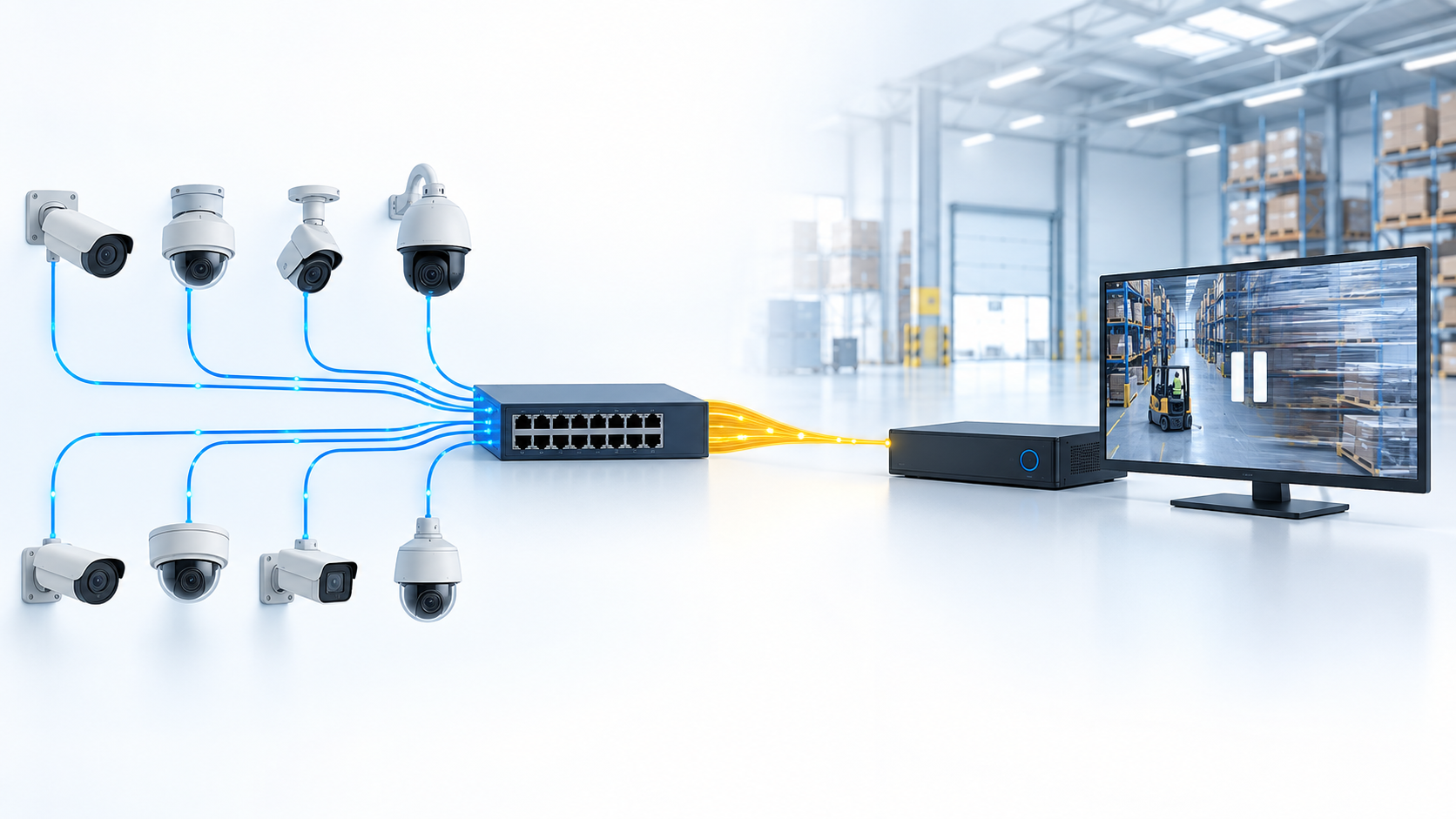
Calculate demand on the link being investigated
Suppose 24 cameras each send an 8 Mb/s recording stream across one access-switch uplink. The combined video payload rate is 192 Mb/s before protocol overhead and other traffic. A 100 Mb/s uplink cannot transport that sustained offered load, regardless of the switch's total backplane rating.
Now suppose six operators each open an additional direct camera stream at 4 Mb/s, and those streams cross the same uplink in the same direction. That adds 24 Mb/s, bringing the illustrative payload total to 216 Mb/s. If those views instead come from a recorder elsewhere, the camera uplink calculation changes. The topology and stream source determine the answer.
For each direction: add only the streams and other traffic that actually cross that link.
A full-duplex link has separate transmit and receive capacity. Do not add both directions together and compare the sum with one direction's line rate. Also avoid treating an estimated payload sum as exact wire utilization: framing and protocol overhead, traffic shape and measurement definitions matter.
These figures are a planning example. They are not a camera-count limit for every 100 Mb/s or Gigabit installation. Camera settings, scene content, codec behavior and the number of requested streams can all change demand.
Average bitrate can hide the event that breaks viewing
A quiet scene is a poor representation of a busy entrance or moving machinery. Axis's bitrate-control white paper distinguishes variable, maximum and average bitrate control. The practical implication is that an average or storage-oriented target should not automatically be treated as a hard ceiling on instantaneous network demand.
Collect traffic during the problematic activity: multiple viewers opening, playback export, a busy scene or another repeatable trigger. Use the shortest reliable measurement interval available and inspect queue or discard information where supported. A five-minute average can look comfortable while shorter bursts exhaust a queue.
If a maximum bitrate is reduced as a diagnostic test, inspect the resulting image quality at the required scene conditions. Reducing traffic until the network stops dropping packets does not establish that the security requirement is still met. Keep an accepted image-quality configuration with the capacity record.
Read counters as evidence, not as a verdict
| Observation during the fault | Useful next investigation | What it does not prove alone |
|---|---|---|
| Rising egress discards on the shared uplink | Offered load, queue behavior and output capacity | That every missing frame was lost there |
| CRC or frame errors on one physical link | Cable, termination, interface and transceiver condition | That the link is simply too slow |
| Stable network counters but recorder overload indications | Ingest, storage and server resources | That the network is healthy at every unmeasured point |
| One viewing station freezes while recording remains intact | Client decoding, display and its own path | That the camera stream is defective |
| Camera uptime resets | Power, watchdog and device restart events | That congestion caused the restart |
Record counter changes over a defined interval. A large cumulative count may belong to an old fault or a long service period. Where appropriate, take a baseline and compare the increase during a reproducible test. Keep the timestamp and interface identity so a later engineer can follow the same evidence.
Switch diagnostic features vary. Cisco's industrial-switch documentation illustrates available management and traffic-monitoring functions for that platform. Confirm equivalent counters and observation options on the actual proposed model rather than copying commands across vendors.
A controlled reduction test can locate the shared limit
In an approved test window, reduce one known part of the load and watch whether the symptom changes. For example, close the additional direct-view sessions while leaving recording active. If the shared uplink discards and viewing interruptions fall together, the result supports a capacity hypothesis.
Then restore the load and confirm that the behavior is repeatable. A single improvement after an unrelated restart is weak evidence because several variables changed at once. Record what was changed, the duration and the observations on both sides of the suspected bottleneck.
Avoid making permanent quality reductions before the bottleneck is understood. A switch replacement may be appropriate, but the recorder's network interface, an intermediate converter or a mis-negotiated cable can impose the same limit. Upgrading only the access switch will not increase a downstream 100 Mb/s connection.
Decide which remedy changes the limiting path
A faster compatible uplink increases capacity only where it is installed. Separating traffic paths may help if the topology and recorder design support it. An application change that avoids unnecessary direct sessions can reduce duplicated traffic without changing camera quality.
Link aggregation deserves particular care. Depending on the implementation and hashing method, traffic is distributed by flows; one flow is not generally split into a guaranteed multiple of a member link's speed. It is not a substitute for checking the load distribution and the capabilities at both ends.
QoS can protect selected traffic during contention, but it does not manufacture bandwidth. If all admitted video is essential and the sustained load exceeds the path capacity, prioritizing it all cannot solve the arithmetic. Define which service may be delayed or reduced before relying on a priority policy.
What to specify when selecting the switch
For a TODAHIKA switch inquiry, provide the camera count, required stream settings, recording topology, additional-view behavior and expansion case. Identify uplink media and the intended speed at both ends. Request the exact port configuration and the counters needed for commissioning.
Keep PoE capacity in the same project worksheet but as a separate check. A switch can have enough watts and insufficient uplink capacity, or adequate bandwidth and insufficient power. Neither specification compensates for the other.
The acceptance test should combine the required recordings, live views and playback or export activity that the site expects to run together. Review useful video at the receiver while watching the relevant links and recorder. Save the configuration and traffic evidence. The result should demonstrate the required service under a named workload, rather than merely show that all cameras can be pinged.
Post time: Sep-20-2026


