
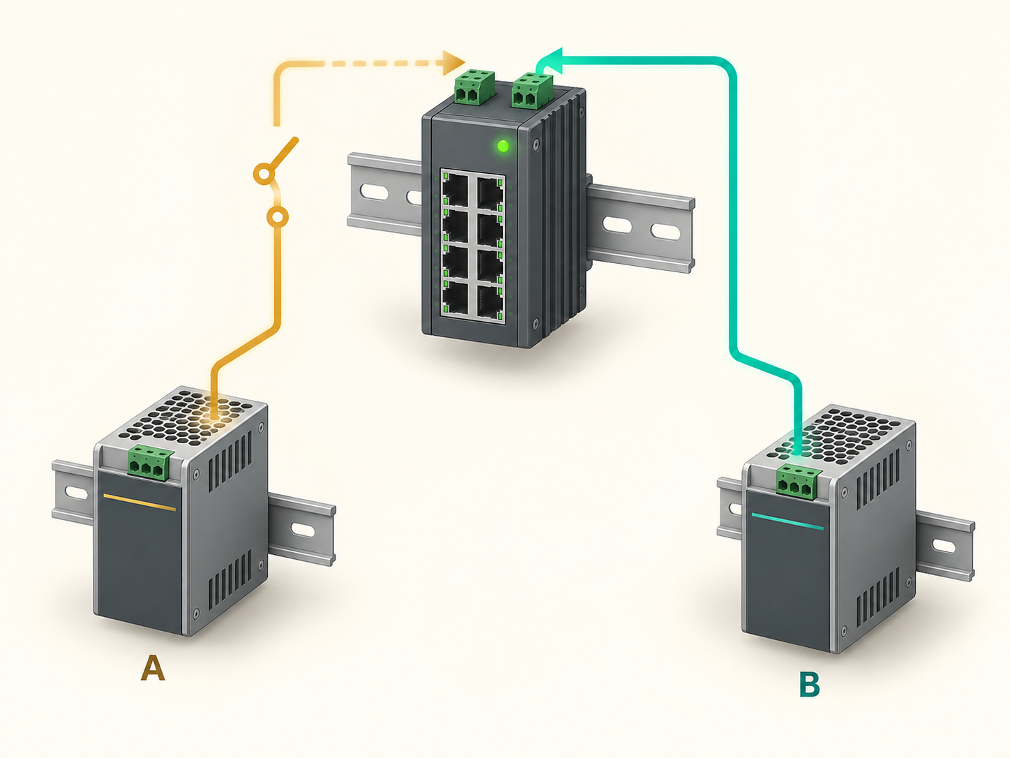
Two DC input connectors are visible on the switch. Two supplies are listed in the bill of materials. The project drawing is marked “redundant power.” Before accepting that claim, ask what remains running when one defined component fails.
Redundancy is a property of the complete arrangement. It depends on the independence of the relevant paths, the capacity of the surviving path and the equipment's behavior during the transition. A duplicated component can reduce one failure risk while leaving a shared upstream dependency untouched.
For an industrial Ethernet network, the acceptance boundary should include useful service. A switch that retains its management page while essential PoE cameras restart has not necessarily met the project's continuity requirement.
Define the failure you intend to survive
Write a specific statement before choosing the topology. For example: loss of either approved DC supply must leave the switch and eight named essential endpoints operating within the agreed service-interruption limit. That is testable. “Dual power for high reliability” is not.
The required protection may concern a failed supply, a disconnected branch or a wider upstream outage. Those are different cases. Two supplies on one upstream circuit can provide protection against certain individual supply failures while still sharing the circuit as a common dependency.
Do not call that arrangement useless; describe its scope accurately. A project may intentionally accept the shared upstream source. The important step is to keep that limitation visible in the design and handover so another team does not assume a broader protection level.
Trace both paths beyond the switch terminals
Start at each input and work upstream through the terminal blocks, branch protection, conversion devices, supplies and source distribution. Mark where the paths are separate and where they meet. Include a shared UPS or DC distribution unit if it sits in both paths.
Then examine the local common points: one removable connector, one terminal block, a shared return arrangement or one cable route may matter to the specified failure case. The review should follow the actual installation and approved electrical design rather than a simplified drawing with two arrows.
The TODAHIKA TH-G510-8E2SFP product page lists dual DC inputs and distinguishes the PoE and non-PoE input ranges. That listing is a starting point for model selection. Obtain confirmation of input isolation, source behavior and the intended operating arrangement for the exact model; dual inputs alone do not establish current sharing or a particular redundancy architecture.
Capacity sharing and redundancy answer different questions
Suppose the essential DC demand is 180 W. Two 120 W supplies may have a combined nameplate total of 240 W, but one 120 W supply cannot sustain the 180 W load alone. Even if a supported arrangement allows capacity sharing, the loss-of-one-source requirement remains unmet unless the system intentionally reduces its load.
Conversely, two appropriately rated supplies can support a redundant arrangement when each surviving path meets the required load and the topology is approved. Check available output at the actual voltage and temperature, not only the nominal wattage printed on the housing.
PULS's explanation of paralleling and redundancy is useful for this distinction. It also reinforces the need to use a supported arrangement, including any required decoupling. Do not connect outputs together simply because their voltage labels match.
Where load shedding is permitted, document the essential set and the permitted sequence. The remaining supply must support that set under its relevant operating condition. A policy that sheds the recorder's uplink before nonessential devices would preserve watts while defeating the service requirement.
Check the PoE budget after a source is lost
Power continuity has two layers in a PoE installation: the switch's own operation and the power available to connected endpoints. Ask whether the aggregate PoE budget changes with the source arrangement and how the switch handles an insufficient budget.
An endpoint may continue drawing less than its reserved allocation during an ordinary test. That does not establish the behavior during a cold restart or a higher-demand operating mode. Include the admitted classes and required endpoint functions in the failure-case review.
For example, a design might survive source loss during a quiet daytime camera load but fail when the same cameras enable illuminators. The test load should reflect the accepted essential service, not whichever consumption happens to be visible when the technician removes a feed.
Use a failure matrix instead of one unplugging demonstration
| Controlled test case | What to observe | What the result establishes |
|---|---|---|
| Remove feed A while B is available | Switch uptime, endpoint uptime, service continuity and alarm | Behavior with the tested A-path interruption |
| Restore A, then remove B | The same measurements in the opposite direction | Whether both paths behave as required |
| Start with only the permitted surviving feed | Startup, PoE admission and required application functions | Whether recovery depends on both supplies being present |
| Restore a lost feed during normal operation | Service continuity and alarm clearing | Transition back to the normal arrangement |
| Apply the agreed higher-load case before source loss | Budget, input condition and endpoint behavior | Whether the surviving path supports the specified load |
Perform the tests through an approved safe isolation method and maintenance plan. The table defines observations, not instructions to disturb live terminals. A qualified project team should determine the permitted test points and any limits imposed by the process being served.
Measure the application, not just the front-panel LEDs
A continuously lit indicator can miss a short service interruption. Record the switch's uptime and relevant port events, but also observe what the network carries. For cameras, that may include recording continuity. For other applications, use the appropriate communication or process-level evidence.
Choose the measurement resolution to match the acceptance limit. An occasional ping cannot prove that no brief interruption occurred between probes. Equally, a single missed reply does not by itself identify a power transition as the cause. Correlate the source event with the network and application observations.
If the project permits a finite interruption, state its definition: where it is measured, which traffic is used and how repeated trials are evaluated. Avoid substituting a brochure recovery figure for a measurement of the site's complete service path.
An undetected failed supply leaves a degraded system
Redundancy buys time to repair a failure. If the loss of one path is never reported, the installation can remain on a single surviving path until the next fault. Confirm which input or supply alarms are actually available and how they reach the responsible operator.
Test the alarm as part of the same source-removal exercise. Check that it identifies the correct condition, reaches the intended destination and clears or changes state appropriately after restoration. Document who responds and how the failed component is replaced.
Do not assume that an available relay or an SNMP capability means the required source-loss event is configured. The exact event mapping, supported firmware and monitoring integration need verification on the selected equipment.
Keep the accepted power arrangement reproducible
The handover should identify each supply, branch, connection, setting and essential load. Include the failure matrix, measured outcomes and any shared dependencies that remain. Keep a spare-parts rule that prevents an apparently equivalent lower-rated supply from silently reducing the surviving-path capacity.
When requesting a TODAHIKA industrial Ethernet switch, provide this failure requirement alongside the port count and environment. A supplier can then confirm a specific supported arrangement. The resulting claim is precise: the named system survived the named failure under the tested load, with the required service and alarm behavior.
Post time: Sep-25-2026


