
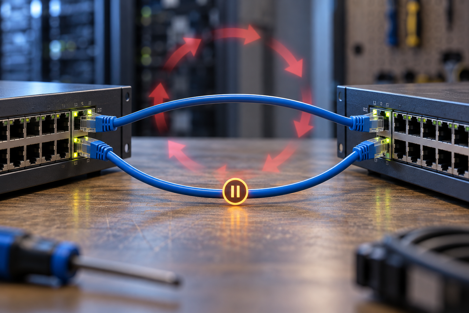
A technician adds a spare cable between two cabinets to improve reliability. Minutes later, unrelated devices become unreachable and switch activity indicators appear continuously busy. The new cable may have created a Layer 2 loop rather than a usable backup path.
Ethernet redundancy needs an appropriate forwarding design. A second physical connection can be useful when supported by the selected spanning-tree, ring or aggregation arrangement. Without the required control, frames can circulate and multiply, consuming capacity and disrupting address learning.
The response should restore the known topology and preserve evidence. Disabling loop-prevention features to make every port appear to forward can make the failure worse.
Distinguish a loop from a busy but valid network
Look for the timing of the fault and the most recent topology change. Rising broadcast or unknown-traffic rates, MAC-address movement and repeated topology events can support a loop investigation. They are clues rather than a complete diagnosis: legitimate movement and other faults can produce some similar observations.
Compare the physical cabling with the accepted drawing. Include small desktop switches, wireless bridges and devices that can bridge two interfaces. A loop may exist outside the cabinets shown on the main network diagram.
In an approved maintenance response, isolate the newly introduced or clearly identified unintended path and observe whether service returns. Keep the relevant events and counters. Randomly removing many links at once can restore service while destroying the information needed to prevent the same incident.
RSTP creates a logical topology over the physical links
Spanning-tree protocols coordinate forwarding so a supported redundant topology does not contain an active Layer 2 loop. Some physical paths may be held out of forwarding until they are needed. That blocked or discarding state can be an intended part of a healthy design.
Check the selected root, port roles and protocol compatibility across the network. A root chosen by accident can produce an unexpected traffic path. Different protocol modes or region settings can also change behavior, so the review must include all participating switches.
Do not assume that enabling RSTP on one device protects a complete mixed network. Confirm the implementation, interconnections and required settings at every relevant point. The topology's normal and failure states should be explainable before it is connected to production services.
Edge-port settings are for the intended endpoint role
An edge-port or PortFast-style setting can allow a genuine endpoint connection to begin forwarding promptly under the platform's rules. It should not be applied indiscriminately to inter-switch links to make startup look faster.
Cisco's PortFast and BPDU Guard explanation distinguishes rapid endpoint forwarding from the protective response to unexpected bridge protocol data units. The exact names and behavior on another manufacturer's equipment require its own documentation.
PortFast is not a general instruction to disable spanning tree. Likewise, BPDU Guard and BPDU filtering are not interchangeable features. Suppressing control information can remove evidence needed for loop prevention; a protective shutdown can instead identify an unexpected bridge connection on a port designated for an endpoint.
Review ports by role: inter-switch, endpoint, shared downstream segment or a device that may bridge interfaces. Record the intended role with the physical label. That makes a future cable move a visible design change rather than an invisible alteration to the network's assumptions.
Redundant links need one coherent control arrangement
Two links between switches may form a supported aggregation group, participate in a spanning-tree design or belong to a specified ring architecture. Those are different arrangements. Configure the intended design at both ends and verify that the equipment supports the chosen combination.
For aggregation, confirm group membership and compatible settings before connecting all members. For a ring, confirm roles and ring-port assignments. For spanning tree, verify the expected root and blocked paths. Do not mix partial configurations from different examples merely because each example contains two cables.
If an unmanaged device is included, evaluate what control traffic it forwards and what role it plays in the topology. Lack of a configuration menu is not proof that the device cannot participate in an unintended loop.
A port-role review catches many preventable faults
| Port role | Review before deployment | Evidence to retain |
|---|---|---|
| Switch-to-switch connection | Supported protocol or aggregation arrangement at both ends | Topology, port roles and configuration |
| Direct endpoint port | Whether the endpoint can bridge or receive an added switch | Intended role and appropriate protection policy |
| Wireless bridge connection | Layer 2 path and any parallel wired path | Complete topology including the radio link |
| Maintenance or spare port | How temporary equipment is admitted | Label, permitted use and recovery procedure |
| Redundant ring connection | Required roles and failure behavior | Normal state plus controlled fault test |
Include the management network in this review. A storm can prevent remote access just when the team needs it most. Establish an approved local recovery method and keep the accepted configuration available outside the affected network.
Test protection in a controlled environment
Use an isolated setup or an approved procedure to verify the relevant failure response. A deliberate loop in a live production network is not a routine acceptance shortcut. The test should demonstrate the configured protection without placing unrelated services at risk.
Observe whether the expected port state or alarm occurs and whether the required service remains available. If a protection feature disables a port, verify the documented recovery process after the unintended connection is removed. Automatic recovery settings should be reviewed against the risk of repeatedly reintroducing the same fault.
Also test a legitimate redundant-path failure. The network should use the intended alternate path and meet the application's continuity requirement. A design that prevents loops but cannot recover the required service still needs work; both conditions belong in acceptance.
Storm control is a supporting measure
Traffic-rate controls can limit selected storm traffic where supported, but they do not replace a correct loop-free topology. Their thresholds and traffic classes need careful selection so required bursts are not discarded unexpectedly.
If storm-control events occur, investigate their cause rather than simply increasing the threshold. A new legitimate service, a faulty endpoint and a switching loop call for different corrections. Retain the affected port, traffic class and timing with the topology evidence.
When evaluating a TODAHIKA industrial Ethernet switch, specify the topology, required loop-prevention behavior, endpoint-port controls and diagnostic needs. Confirm support for the exact model and software revision before relying on a family-level feature list.
The final handover should show which cables are supposed to exist, which paths normally forward and how the network responds to the approved failure cases. With that record, adding a cable becomes a reviewed topology change instead of an experiment whose consequences are discovered by the whole site.
Post time: Oct-13-2026


