
Two Gigabit links are active in the aggregation group, but a single file transfer still stays below one Gigabit per second. The second link is mostly quiet. That result can be entirely consistent with the design.
In a conventional flow-based link aggregation arrangement, the device selects a member link using a hash of supported traffic fields. Keeping a flow on one member helps preserve packet ordering. Multiple suitable flows may use different members, but one flow does not automatically receive the sum of their line rates.
LACP coordinates participation in the aggregation group. It is not a promise that every application transfer will be split evenly across all connected cables. The forwarding implementation and the traffic pattern determine how capacity is used.
Separate three different performance claims
| Claim | What it means | How to test it |
|---|---|---|
| Aggregate capacity | Multiple traffic flows may use multiple members | Generate representative independent flows and observe each member |
| Single-flow capacity | One flow is constrained by its selected path and other limits | Test the actual application's flow behavior |
| Failure capacity | The surviving members carry traffic after a fault | Remove a member in an approved test and repeat the required workload |
A quotation should identify which of these benefits the project needs. A site seeking resilience may accept a reduced capacity after failure. A site seeking a faster single stream may need a faster physical interface instead of more members at the original speed.
The hash sees fields, not your idea of a workload
Depending on the platform, member selection may use source and destination MAC addresses, IP addresses, transport ports or a supported combination. Cisco's flow-based load-balancing guide provides an example using a five-tuple. Other devices offer different choices and restrictions.
If the selected fields do not vary across the workload, traffic can collect on one member. For example, a method based only on a common destination field may see little diversity when many devices send toward the same next hop. Increasing the number of members does not necessarily change that observation.
Inspect the supported method before altering it. A change may affect more than one aggregation group on some platforms and may redistribute established traffic. Use the selected model's guidance and evaluate the effect under a controlled workload.
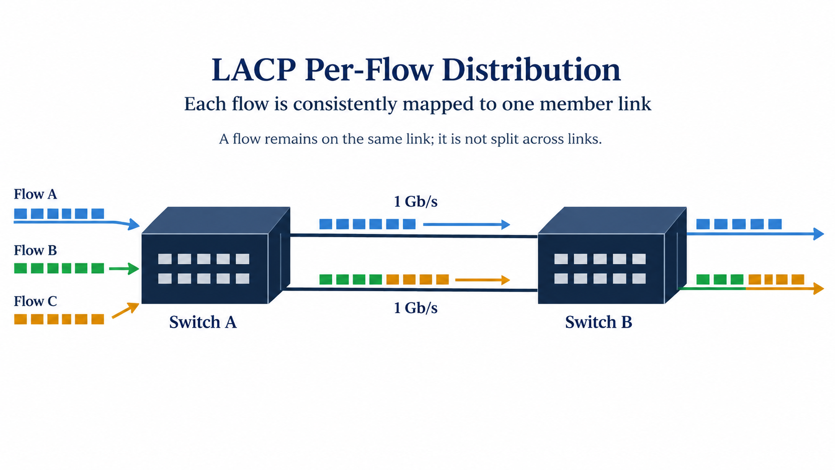
A simple two-link example
Imagine two 1 Gb/s members and four independent offered flows of 400 Mb/s each. The aggregate offered payload is 1.6 Gb/s. If the implementation maps two flows to each member, the payload distribution is 800 Mb/s per member before relevant overhead.
If three flows map to one member and one to the other, the offered payload becomes 1.2 Gb/s on one link and 400 Mb/s on the other. The busy member cannot carry that sustained offered rate, even though the group has unused capacity elsewhere. The figures illustrate distribution, not a predicted hash result for a particular switch.
This is why a group-level utilization number can conceal a constrained member. Inspect individual member rates and discards. Also distinguish offered traffic from delivered throughput; a source attempting to send a rate does not establish that the receiver obtains it.
Do not infer the flow count from the number of applications
One application can open several transport sessions, while many user actions may be carried within a smaller set of flows. A tunnel can also change which fields are visible to the switch's hashing function. The traffic seen on the uplink matters more than the number of windows open on a workstation.
Test the production-representative pattern. A benchmark with many parallel sessions may demonstrate useful aggregate capacity while saying little about a single camera stream, backup session or other large transfer. Conversely, a single-session test can understate the benefit for a site with many independent endpoints.
Keep the test definition with the result: number of flows, endpoints, protocol, direction and offered load. That makes a later throughput claim reproducible instead of presenting one large number without its traffic conditions.
Confirm group formation before blaming the hash
Check which physical links are actually participating and forwarding in the intended group. A cable can be up while its interface is not a usable member. Review the partner identity, selected state and configuration consistency using the platform's supported status information.
Compare speed, VLAN handling, relevant MTU settings and other required member properties. Confirm the intended dynamic or static aggregation mode at both ends. Two parallel links with only one end configured correctly can create a different and potentially disruptive topology.
Do not connect an ordinary aggregation group to two independent switches and assume they form one logical partner. A supported multi-chassis or stacking design is a separate capability with its own requirements. Specify and verify it explicitly when chassis-level redundancy is needed.
Test the capacity left after one member fails
Return to the 1.6 Gb/s offered-load example. If one of two 1 Gb/s members is lost, the surviving link cannot carry that sustained total unchanged. Successful group failover therefore does not establish that every application retains its original performance.
Define the essential failure workload and any permitted reduction in nonessential traffic. Then exercise member loss and restoration through an approved procedure. Observe useful service, member state, discards and the time taken for the relevant traffic to stabilize.
If a minimum-member setting is available and relevant, review its intended effect. Some designs prefer a group to go down when too little capacity remains so another path can be used. The right choice depends on the wider topology and must be tested there.
When a faster physical uplink is the clearer choice
If a required individual flow needs more than one member's usable capacity, compare an appropriately faster interface and compatible equipment at both ends. If many smaller flows need aggregate capacity or the project needs link redundancy, aggregation may fit well.
Make the comparison with the actual traffic and failure requirement. Include optical modules, port availability and downstream bottlenecks. A faster uplink cannot increase a recorder or server's own processing limit, and a larger aggregation group does not remove a slower interface later in the path.
For the TODAHIKA Layer 2 managed-switch range, request confirmation of the exact model's aggregation mode, member limits, load-distribution controls and diagnostic visibility. Supply the application's flow pattern with the inquiry. The accepted result should state both normal-operation throughput and the service available after the agreed member failure.
Post time: Oct-16-2026


