
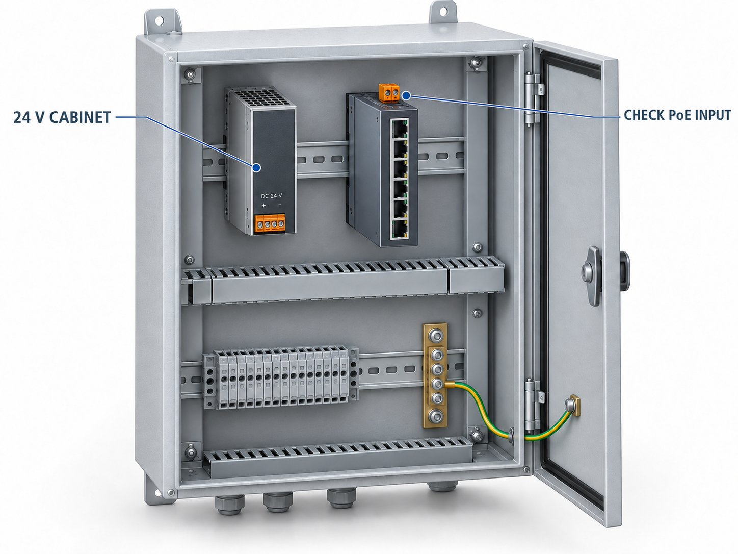
A machine cabinet already has a 24 V DC supply. The new Ethernet switch fits the DIN rail, its enclosure looks identical to the existing non-PoE model, and the camera needs only one network cable. It is tempting to treat the upgrade as a straightforward replacement.
The decision depends on the complete ordering code. Some industrial PoE switches accept a low-voltage input and include the necessary conversion. Others require a higher DC input for PoE operation. A wide input range listed for a related non-PoE model cannot be carried across to the PoE version.
For a cabinet builder, the useful question is therefore not simply whether a switch is described as industrial. It is whether the exact switch, supply and powered devices form a supported electrical system under the intended load and temperature.
A real product-page distinction worth checking
The ordering information on the TODAHIKA TH-G510-8E2SFP page distinguishes two DC variants: the TH-G510-2SFP non-PoE model is listed with a 9–56 V DC input, while the TH-G510-8E2SFP PoE model is listed with a 48–56 V DC input. The wider range belongs to the non-PoE variant.
That distinction rules out specifying the listed PoE model as a direct 24 V input solution on the strength of the family page alone. Obtain the current model-specific datasheet and written input confirmation with the quotation. Do not energize equipment outside its approved input range to see whether the management interface happens to start.
This is also why the statement “the switch runs at 24 V but the cameras do not” needs careful interpretation. It may describe a different product architecture, a misidentified variant or operation outside a supported range. It is not a general promise that every higher-input PoE model will run its switching electronics correctly at 24 V.
Follow the complete power path
Start at the cabinet supply and work toward the endpoint. Record the nominal voltage, permitted variation and available continuous output of the existing supply. Then record the switch's approved DC input, the PoE capability of each proposed port and the input requirement of each powered device.
These are separate interfaces. The cabinet's 24 V rail supplies the switch or a converter. A standards-based PoE port then supplies a compatible powered device through the Ethernet channel. The voltage and power at one interface do not automatically describe another.
Cable loss and conversion loss also occur in different places. If a DC converter sits between the cabinet supply and the switch, its input demand is higher than its delivered output whenever efficiency is below 100%. Losses along the Ethernet channel affect the source-to-device relationship further downstream. Keep these boundaries named in the calculation so the same allowance is neither missed nor counted twice.
Three viable architectures to compare
| Arrangement | What the supplier must confirm | Main integration question |
|---|---|---|
| A PoE switch explicitly supporting the cabinet's 24 V input | Input tolerance, available PoE budget and temperature conditions | Is the stated budget available at the lowest approved input? |
| An approved DC-DC converter feeding a higher-input PoE switch | Converter output range, continuous capacity, protection and compatibility | Can the existing 24 V supply and distribution carry the converter's input demand? |
| A separate approved supply for the PoE branch | Required switch input and complete power-path ratings | Does the cabinet have the space, thermal capacity and appropriate distribution for it? |
Choose between these arrangements using the completed system, including accessories and commissioning work. A low-cost switch that requires an additional converter, protection arrangement and larger upstream supply may not offer the lowest installed cost. Conversely, a separate supply may be justified when it provides a clearly documented power branch and simplifies maintenance.
The design review should include how the branch is isolated for service and how a replacement is identified. Two similar DIN-rail supplies set to different voltages are a maintenance risk if the cabinet labels and spare-parts list are vague. Specify the output and destination on the drawing, not merely “network power.”
A 24 V current calculation that changes the discussion
Consider an illustrative system needing 180 W at the converter's output, including the switch and its planned PoE load. Assume 90% converter efficiency at that operating point. The converter then needs approximately 200 W at its input: 180 W divided by 0.90.
At 24 V, 200 W corresponds to about 8.33 A. If the approved input range permits operation at 21.6 V and the same input power is required, current rises to approximately 9.26 A. These are calculation examples, not specifications for any TODAHIKA product or converter.
Now suppose the cabinet's existing 24 V, 10 A supply already serves 5 A of control loads. Its nominal remaining capacity is only 5 A before checking derating and other conditions. Adding a converter that needs more than 8 A is not justified by the fact that the new switch's output voltage looks correct.
The next step is to use the selected components' actual data: minimum input, efficiency curve, continuous current, temperature derating and approved connection requirements. Include the existing control load's worst relevant operating state. A cabinet measured while motors, valves or accessories are idle may conceal the case that matters during production.
Startup and protection deserve their own check
Steady-state arithmetic does not describe every startup event. A supply or converter can react differently when the switch and its connected devices restart together. The result may be a voltage dip, a protection event or repeated attempts to start.
Power-supply protection is model dependent. MEAN WELL's technical FAQ describes several approaches, including current limiting, pulsed recovery and shutdown. The practical lesson is to obtain the selected unit's behavior and recovery conditions; it is not to assume that all supplies will automatically recover in the same way.
Keep the investigation controlled. First confirm the approved electrical arrangement. Then test the planned startup sequence and inspect the supported status information. If every device repeatedly restarts, changing the camera watchdog timeout will not solve a supply that cannot sustain the startup load. If only one endpoint fails while the DC input remains within limits, investigate that branch separately.
The PoE endpoint still needs a compatibility check
A correct switch input does not establish that every connected device receives the power it requires. Check the endpoint's supported PoE type and class, the selected port's capability and the aggregate budget under the chosen supply arrangement. “PoE” on both product descriptions is too broad to settle those questions.
The Ethernet Alliance's PoE technical brief distinguishes source and powered-device capabilities. Use those interfaces when comparing requirements. A passive 24 V radio, for example, needs its own approved powering arrangement; it should not be treated as interchangeable with a standards-based powered device simply because both use an RJ45 connector.
Build a port schedule before ordering. It should connect each physical switch port to an endpoint model, a required function and an approved power mode. Include features that change demand, such as a camera illuminator or an AP accessory. This turns a general compatibility assurance into a combination that can actually be demonstrated.
What to include in the cabinet acceptance test
Test with the final supply and converter arrangement, the planned endpoint mix and representative installed cables. Record the input condition and cabinet temperature alongside the operating results. A successful test with a different bench supply proves a different combination.
Exercise simultaneous startup where the application requires it. Enable the endpoint features included in the purchase specification and check both device uptime and useful service. If redundant inputs are part of the design, carry out an approved loss-of-feed test and confirm what the remaining path must support. Two terminal pairs alone do not establish the required failure behavior.
Finally, retain the complete bill of materials, settings, model revisions and accepted load. Set a clear change rule: a different converter, increased endpoint demand or a materially hotter cabinet requires review. That record makes a future expansion much easier to assess than a note saying only that “24 V PoE worked in the workshop.”
Information to send with a 24 V PoE inquiry
For a quotation, provide the actual cabinet input range, available current after existing loads, highest relevant internal temperature, endpoint models and required functions. Ask for the exact switch code, approved supply arrangement and available PoE budget under those conditions.
If the proposed answer includes a converter, request it as a named line item with its own operating limits. If it changes the upstream supply, include that change in the quotation and drawing review. The right purchasing outcome is an identifiable, supportable power system whose limits remain clear after the cabinet leaves the workshop.
Post time: Sep-11-2026


