
An eight-port switch looks sufficient for eight devices until the design also needs an uplink. Add a second connection for redundancy, a maintenance interface or a shared copper/SFP combo arrangement, and the available endpoint count can be lower than the number the buyer first had in mind.
Port planning should start from a connection schedule. Count the logical interfaces required for every role, identify their media and speed, and then check power and traffic capacity separately. The result is a usable design rather than a match between two headline numbers.
Count infrastructure connections before allocating endpoints
List uplinks, ring connections, aggregation members and other infrastructure roles first. These interfaces are part of the topology even if no camera, AP or controller plugs into them. A redundant path may consume an additional port while also changing the required management functions.
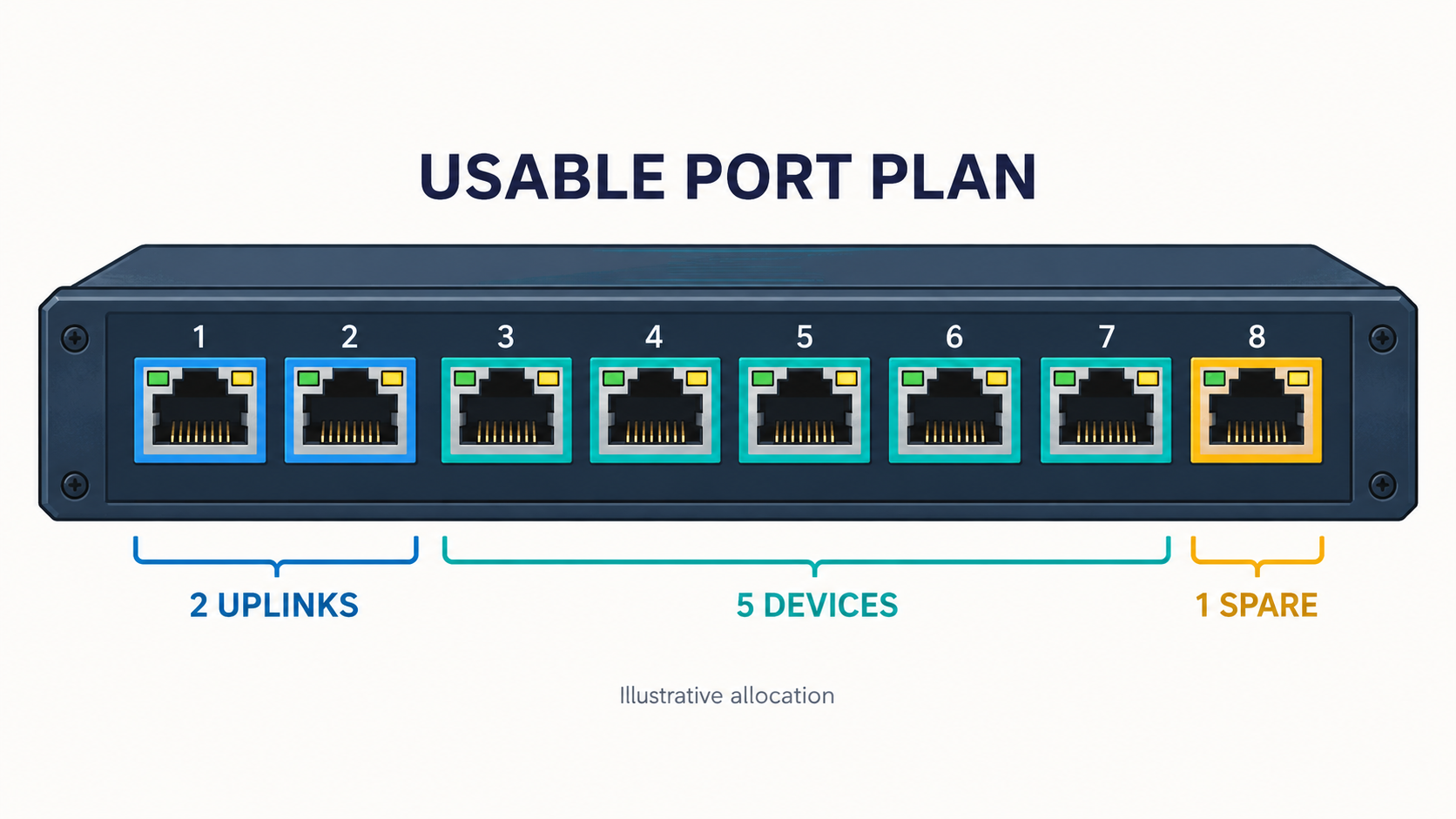
In an illustrative switch with eight independent ports, allocating two to uplinks leaves six. If one of those six is reserved for an agreed maintenance or expansion use, five remain for the initial endpoints. The arithmetic is simple; the common mistake is leaving the infrastructure roles out of the count.
A reserved maintenance port is a design choice, not a universal requirement. Some sites use an existing approved management path instead. State the reason for each reservation so another engineer can distinguish a necessary role from an arbitrary allowance.
Distinguish physical connectors from logical interfaces
A combo port can offer copper and SFP connection options for one logical interface, with usage determined by the model’s design and configuration. Two visible connectors do not necessarily provide two simultaneous independent links. Read the exact port map and operating instructions.
TODAHIKA’s TH-GC080416M2 listing distinguishes dedicated SFP interfaces, combo interfaces and separate copper ports. That kind of breakdown is more useful than counting the openings on the front panel. Confirm simultaneous-use rules and the complete order code before assigning connections.
Also separate dedicated management, console and service connectors from data-forwarding ports. A console connection does not add an Ethernet endpoint interface. A management interface may have a different role from an ordinary switch port, depending on the platform.
Match the media and speed to each role
A total count can be adequate while the mix is wrong. A cabinet needing two fiber uplinks and seven copper connections cannot be evaluated from “nine ports” alone. Identify SFP-host speeds, copper modes and any restrictions on the proposed modules.
Include the actual peer devices. A port that supports the required nominal speed may still need an approved optic or specific configuration. Legacy 100 Mb/s devices and Gigabit fiber peers should appear as separate requirements rather than a vague request for “Gigabit throughout.”
Use a schedule such as this, replacing the illustrative entries with the actual project:
| Connection role | Quantity | Media and function to confirm |
|---|---|---|
| Camera endpoints | 5 | Copper speed and required PoE type/power |
| Primary uplink | 1 | Fiber or copper, supported speed and traffic demand |
| Redundant uplink | 1 | Media plus the approved redundancy behavior |
| Reserved connection | 1 | Reason for reservation and required future capability |
| Total logical interfaces | 8 | Independent availability in the selected model |
The table does not prove that any particular eight-port model meets the design. It makes the questions visible: whether the interfaces are independent, whether the right media are available and whether the required features exist.
Count PoE capacity on two levels
A spare copper port is not automatically a spare powered port. Confirm which interfaces provide PoE and the supported type or class at each one. Then compare the combined device demand with the total available budget under the approved power-input conditions.
For an illustrative case, five devices requiring 18 W each at the relevant planning boundary total 90 W before any additional allowance required by the design. Adding a sixth powered endpoint changes the power calculation even if a physical port is available. Keep PSE output and PD input quantities distinct when selecting the budget and accounting for cable losses.
Check startup and enabled high-power modes as well as steady operation. The reserve should be tied to a documented expansion or load assumption. An unused interface alone cannot establish that the supply or thermal arrangement has capacity for another powered device.
Count traffic where it converges
Several access ports can share one uplink. Estimate the concurrent traffic that crosses that uplink, including application bursts, playback or uploads where relevant. The sum of endpoint port speeds is not the actual workload, but ignoring aggregation can produce an undersized path.
A second uplink used for redundancy may be blocked or otherwise unavailable for simultaneous forwarding in the chosen design. Do not add its nominal speed to the normal usable capacity unless the architecture actually uses it that way. Link aggregation also has per-flow distribution behavior that should be considered separately from the bundle’s aggregate capacity.
If an uplink fails, check whether the remaining path can carry the required service. A design may be redundant in connectivity while becoming overloaded under the defined failure condition. Port availability and resilient capacity are different acceptance questions.
Reserve for a defined future, not an unspecified percentage
Ask what expansion is reasonably expected: more cameras, an additional AP, another fiber route or a diagnostic connection. Those additions may require different resources. Reserving two copper ports does not prepare for a future optical uplink if the switch has no available compatible SFP interface.
Document both physical and functional reserve: interfaces, PoE power, uplink traffic and any required management capacity. Review the cabinet’s space, supply and thermal conditions at the same time. A larger switch can change more than the port count.
Avoid overbuying solely to avoid making a forecast. A clear initial design with a documented expansion path can be preferable to an oversized unit whose unused features add cost or maintenance complexity. Compare the options against the actual deployment plan.
Make the final port map part of the order and handover
For TODAHIKA network switch selection, provide the connection schedule, media, power demand and redundancy plan. Request a model-specific port map showing how every required role is assigned, including combo limitations and reserved interfaces.
Carry that map into installation labels, configuration and acceptance checks. The final answer should show enough usable connections under both normal and required failure conditions, with the power and traffic budgets to support them. That is a more reliable sizing method than choosing a switch from the front-panel number alone.
Post time: Nov-09-2026


