
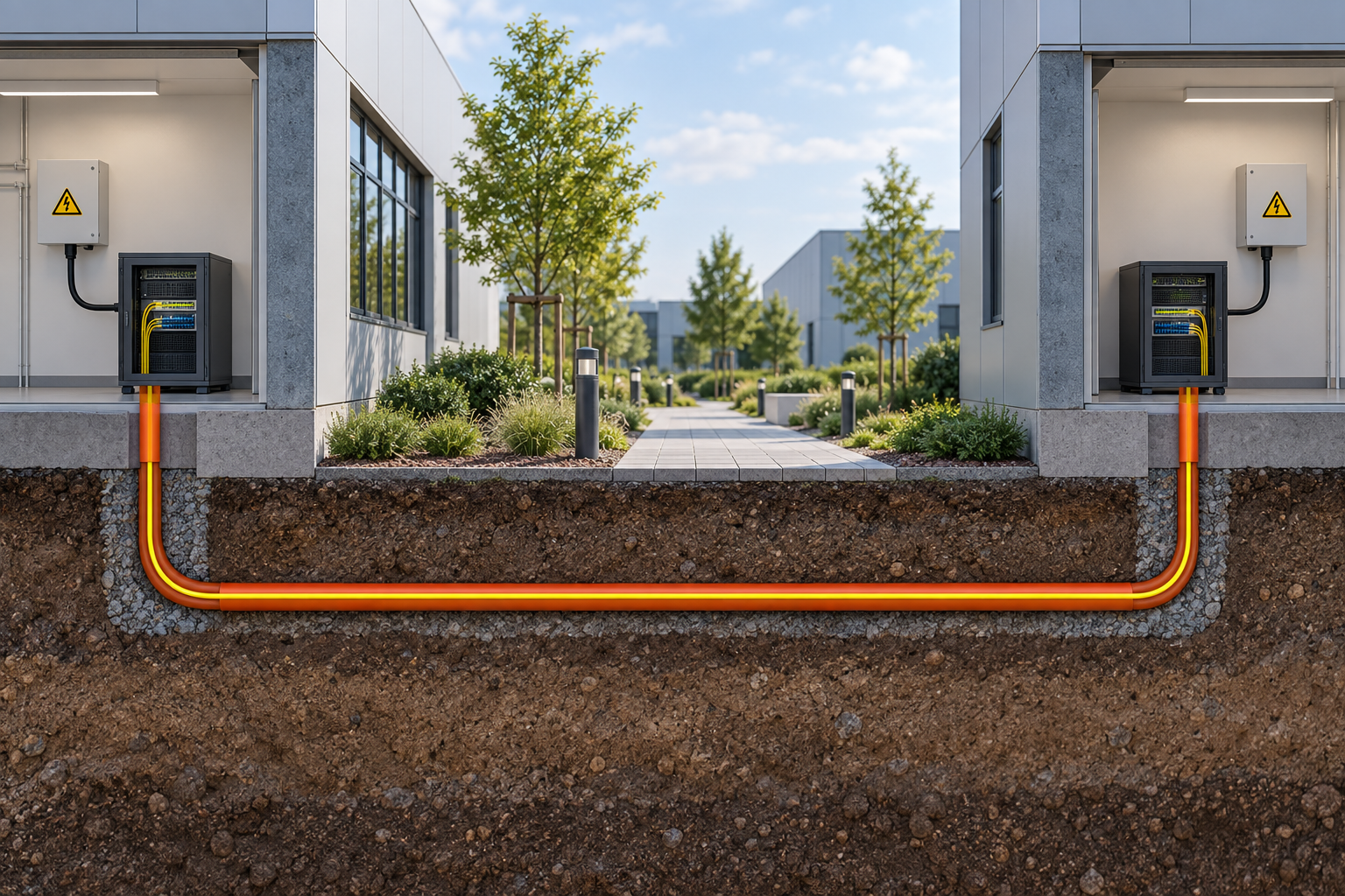
Connecting a warehouse to an office looks like one network link on a drawing. In the field, it becomes a cable route, two optical interfaces, two powered locations and a maintenance responsibility that spans both buildings.
Fiber is often considered for this task because it supports optical data transmission over suitable distances and can avoid an electrically conductive data path when the cable construction is entirely dielectric. That last qualification matters: not every cable sold as fiber optic contains no metal.
The project should therefore specify the complete cable and endpoint arrangement. A pair of SFPs and a distance estimate are only the beginning.
Identify the route and cable construction first
Record whether the route is in a duct, directly buried, aerial or within buildings. Include entry points, termination locations and the relevant installation constraints. Select cable and pathway products appropriate to that route through the responsible project design.
Fiber cable may contain metallic armor or other conductive elements. Corning's outdoor cable portfolio distinguishes construction options, while its dielectric-armored example identifies an all-dielectric design. The exact ordered construction determines the relevant bonding and installation considerations.
Do not assume that the optical core makes every part of the route electrically isolated. Have the cable, armor, support and building-entry arrangements reviewed against the project's applicable requirements. The switch selection cannot settle those construction details.
Decide what the remote building must support
List the remote endpoints and their services. One fixed non-PoE device creates a different requirement from several cameras, wireless access points and controllers. Record the required traffic in both directions and the likely expansion.
Then choose whether the remote endpoint needs a media converter or an SFP-equipped switch. The decision should include port count, management, VLAN handling, fault indication and PoE where required. Verify those features on the exact proposed model instead of inferring them from “industrial” or “fiber” in the product name.
Keep the building uplink capacity separate from individual access-port speed. Multiple endpoints can collectively require more bandwidth than one copper device. An optical link does not automatically mean a high-capacity link; the hosts and modules determine the supported interface.
Match the optics to the host and the installed path
Confirm the interface rate, fiber type, wavelengths, connector requirements and host support at both ends. If using a single-fiber BiDi arrangement, record the complementary transmit and receive direction of each module. Keep the two ordering codes in the same link schedule.
Prepare an optical budget using the route length, connector pairs, splices and other path components. Check both receiver sensitivity and maximum permitted input. The advertised reach is conditional on the optical specification and supported path; it is not a guarantee for every route shorter than that number.
Request the current documentation for the actual modules supplied with the TODAHIKA industrial fiber equipment. Include cabinet temperature in the inquiry. A module that works on an office bench may have a different environmental limit from the industrial switch beside it.
Each end still needs local power
Ordinary optical fiber does not deliver PoE to the far building. The remote converter or switch needs its own approved supply, and any remote PoE endpoints need power from that local arrangement. If a hybrid cable or another specialized powering system is proposed, evaluate it as a separately specified architecture.
Define what happens during a local power outage. The optical route may remain physically intact while the remote equipment shuts down. If continuity is required, specify the relevant backup power and its supported load and duration rather than assuming that the inter-building fiber creates redundancy.
Include the switch's own consumption and the endpoint demand when reviewing the local supply. Where dual inputs are proposed, trace the sources and establish what one surviving path must support. Two inputs fed from a single failed source do not protect against that source's loss.
Keep enclosure and service access in the cost comparison
A remote switch installed in a suitable equipment room has different needs from one mounted in a damp loading area or an outdoor cabinet. Verify temperature, moisture and ingress requirements for the complete arrangement, including transceivers and supplies.
Consider who can access the equipment when the link fails. If the management path uses the failed connection, the operator may lose the very diagnostics needed to distinguish an optical fault from a power failure. Decide whether an additional observation or access method is justified by the site's service requirement.
Include patch panels, spare fibers, labeling and test access in the project scope. They are easy to omit when comparing only the price of two switches. A clearly identified termination and retained test record can make a later repair far more predictable.
A route checklist for the purchase review
| Decision | Record before ordering |
|---|---|
| Physical route | Length estimate, pathway, entries and termination locations |
| Cable | Exact construction, fiber type/count and installation suitability |
| Optical interfaces | Host ports, module codes, speed, wavelengths and loss limits |
| Remote services | Endpoint count, VLAN requirements, traffic and PoE demand |
| Power continuity | Local supplies, backup requirement and accepted outage behavior |
| Environment | Component limits and the enclosure or room conditions |
| Maintenance | Responsible team, spare identification and required test evidence |
Use the same checklist when evaluating an alternative quotation. A lower equipment price may omit optical modules, local power or required management functions. Mark those differences before comparing totals.
Accept the installed link in layers
First inspect and test the cable installation using the procedure and limits appropriate to the selected fiber system. Retain the route and termination identities with the results. Fluke Networks' fiber-testing overview distinguishes inspection, loss measurement and fault-location tools; choose the evidence required by the project rather than treating them as interchangeable.
Next establish the optical interfaces and record the supported operating diagnostics where available. Verify traffic in both directions, the intended VLAN path and the actual remote services. If multicast or another specific traffic type is required, include it in the acceptance workload.
Finally, exercise the approved power-loss and restart cases at each end. Confirm that service and monitoring recover as intended. A daytime throughput test alone does not establish unattended recovery after a building outage.
The handover should allow a replacement technician to identify the cable, the correct optical member at each end, the local power arrangement and the accepted configuration. That is what turns an inter-building fiber installation into a supportable network link throughout its service life.
Post time: Oct-20-2026


