
A driver can have a strong Wi-Fi signal at the parking entrance and lose the connection before reaching the payment machine. Moving the access point a few meters may help one aisle while leaving the next behind a concrete wall. Increasing transmit power can make the network name more visible without fixing the connection.
Parking lot Wi-Fi needs a design that follows the building, the vehicles, and the tasks people carry out. For integrators quoting underground garages and outdoor lots, the first decision is where reliable service is required. AP quantity comes later.
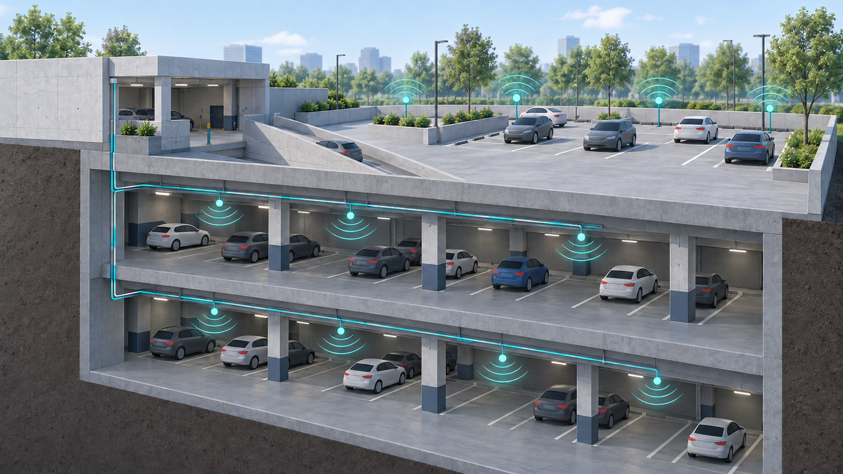
Editorial illustration. Connection symbols show a design concept, not measured coverage or an actual installation.
Define the service before marking AP locations
Write down what the network must support. Visitor internet access, attendants’ handheld terminals, maintenance tablets, and wireless cameras have different traffic patterns. A busy pedestrian exit may need more capacity than a much larger area of parking bays.
Turn those uses into a coverage schedule. Include payment areas, pedestrian routes, lift lobbies, loading entrances, and any spaces where a driver must connect from inside a parked vehicle. Record whether an application must remain connected while moving between levels. A fixed camera should be evaluated for a wired connection before adding its continuous traffic to shared Wi-Fi.
Agree which areas are outside the scope as well. A proposal that promises “full parking coverage” leaves too much open to interpretation when stairwells, service rooms, and the far side of a boundary wall enter the acceptance discussion.
Survey the obstructions people will actually encounter
Concrete, structural steel, columns, and metal services affect signal propagation. A clear aisle and a row of occupied parking spaces are different radio environments. Cisco’s wireless site survey guidance identifies building materials and obstacles as factors that must be assessed on site.
Use the floor plan for an initial design, then check candidate mounting points with temporary equipment. Include the entrance ramp, the spaces behind columns, and the approach to payment terminals. Survey under representative vehicle occupancy wherever possible. Test a phone at normal hand height and, if required by the scope, from inside a vehicle. A laptop held above nearby cars is a poor stand-in for that use.
The return path matters. A phone may receive an AP clearly but lack the transmit power or antenna performance to send data back reliably. Passive signal maps do not fully describe this uplink behavior; an active survey sends traffic through the connection. Cisco’s WLAN deployment survey guide explains both the distinction and the effect of AP/client power imbalance.
Give underground zones a dependable path upstream
Treat each floor and obstructed section as a candidate coverage zone. Position APs to serve the people and devices within those zones, then connect them to the network through planned cable routes.
For an illustrative garage with two basement levels and an outdoor entrance, the design might use a fiber backbone to accessible distribution points, with local PoE switching feeding nearby APs. This is an architectural example, not an AP count recommendation. Actual switch locations depend on cable distances, cabinet conditions, power, access, and the measured wireless layout.
Fiber can be useful where the route between distribution points is long or electrical isolation is needed. The local AP still needs power: a fiber uplink does not replace a PoE switch or another supported power source. Include cabinets, optics, patching, power supplies, and spare capacity in the bill of materials.
Mesh remains an option where cable installation is impractical, but its backhaul needs its own viable radio path. A mesh node behind a concrete slab cannot relay a dependable service through an already poor upstream link. Shared-radio forwarding and additional hops can also consume capacity. The Meraki mesh deployment guide discusses these constraints. Test the proposed link under load; do not assume a universal percentage loss for every mesh architecture.
Design the outdoor section around mounting and power
Outdoor coverage is more than choosing a weather-resistant enclosure. Evaluate mounting height, antenna direction, nearby buildings, trees, parked vans, and the locations where users will stand. A high mounting position can clear an obstruction but may also put intended users outside the strongest part of the antenna pattern.
Check the complete installation against the chosen model’s instructions: operating temperature, cable sealing, mounting hardware, grounding, surge protection, and approved power arrangements. An IP rating addresses enclosure protection under defined conditions; it does not approve the entire installation. The Meraki MR76 installation guide, for example, lists environmental limits and installation requirements separately. Its model-specific values should not be transferred to another manufacturer’s AP.
Verify the PoE requirement per AP and the switch’s total available budget with all intended devices connected. Confirm whether power is available continuously at outdoor poles; a lighting circuit that switches off during the day can undermine an otherwise workable design.
Make acceptance measurable
Define acceptance before installation. Use thresholds appropriate to the actual clients and applications, including signal quality, packet loss, throughput, and roaming behavior where mobility matters. A single internet speed test cannot isolate wireless performance from the WAN connection.
For the handover, record these results by zone:
| Test | Evidence to retain |
|---|---|
| Join and obtain connectivity | Association, address assignment, DNS, and portal results |
| Use the required application | Successful transactions or sessions at agreed locations |
| Move along an agreed route | Connection interruptions and application behavior |
| Operate with representative load | Test client count, traffic, and observed performance |
| Recover from an agreed interruption | Restoration time and affected services |
Keep the final AP map, cable and switch-port records, configuration backup, and a short fault-isolation guide with the results. When a payment terminal later loses service, the operator should be able to identify its AP, power source, and upstream connection.
For a parking network equipment enquiry, send toda the floor plans, service areas, client types, available cable routes, and installation environment. These details provide a useful starting point for discussing APs, switches, controllers, and fiber equipment alongside the local integrator’s survey.


