
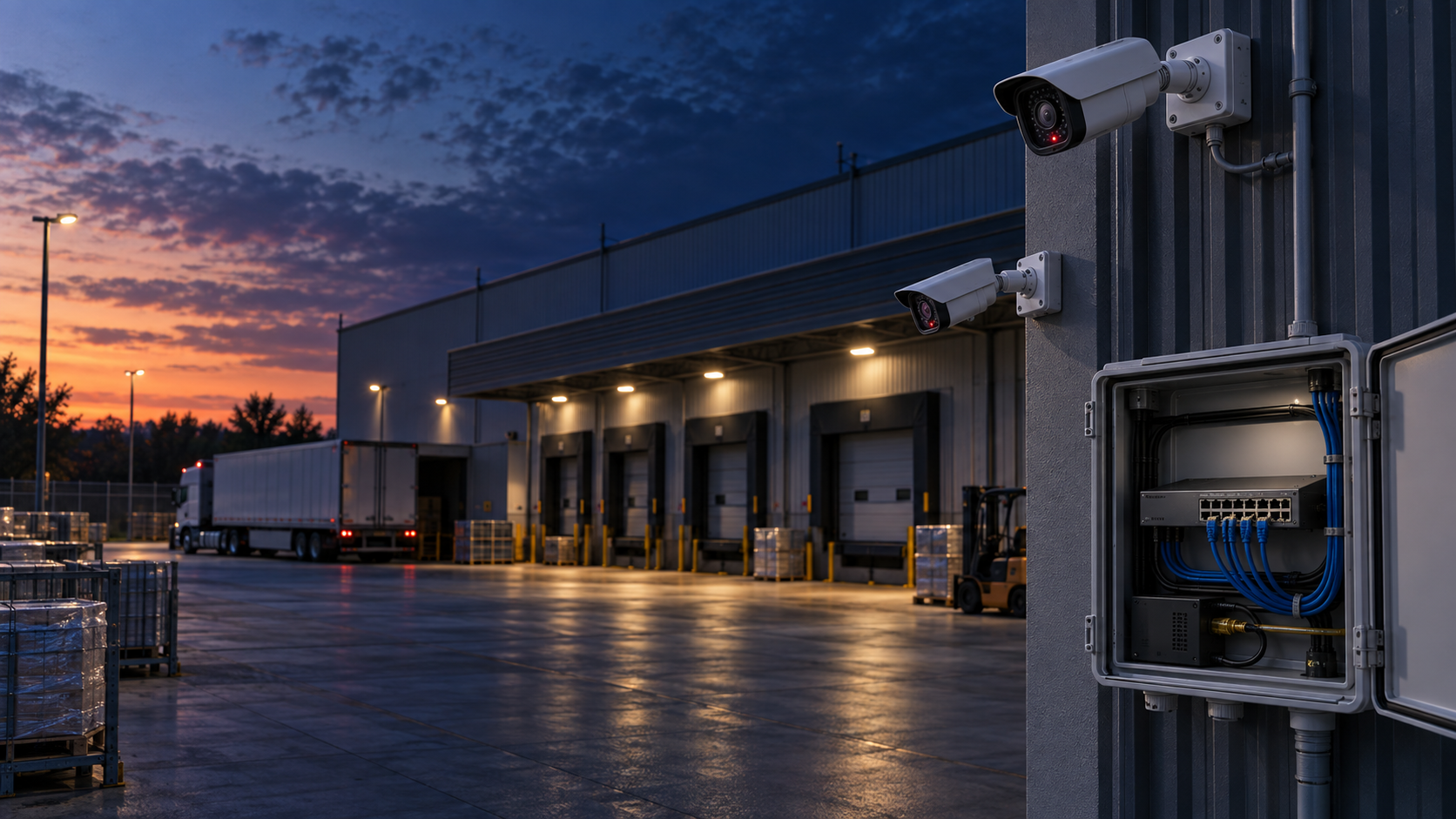
Eight cameras work through the afternoon. After sunset, several disappear from the recorder, recover and disappear again. By morning, the fault is difficult to reproduce. Replacing the cameras may leave the underlying problem untouched.
Night operation can change both electrical demand and video traffic. Infrared illumination and heaters can increase power requirements, while a noisy low-light image can change the bitrate of a variable-bitrate stream. The useful first question is therefore precise: did the camera restart, did its Ethernet link drop, or did only the video session fail? Each observation leads to a different investigation.
This guide develops a diagnostic sequence for integrators and maintenance teams, followed by a purchasing and acceptance checklist. The numerical example is a planning illustration, not a TODAHIKA product rating or a report of a completed customer installation.
Start here: preserve camera uptime, switch port events and recorder timestamps before restarting anything. A stable daytime image does not validate the worst-case power design.
Separate a camera reboot from a missing video stream
“Offline” is an application message, not an electrical diagnosis. Compare at least two independent observations. Camera uptime that returns to zero supports a restart hypothesis. A PoE power-off event recorded at the same time strengthens it. A camera that remains reachable, with continuous uptime, while only its recorder session fails needs a different investigation.
| Observation during the fault | First investigation | Evidence worth saving |
|---|---|---|
| Camera uptime resets; PoE port reports overload or power denial | Per-port capability, allocation policy and total power budget | Port event, allocated watts, supply condition |
| Several cameras restart together; switch uptime is continuous | Shared PoE budget or source limitation | Number of affected ports and simultaneous load |
| Switch and cameras all restart | Cabinet supply, protection or upstream power interruption | Switch uptime, supply alarms, event sequence |
| Camera uptime continues; recording or live view stops | Uplink congestion, recorder or video-session fault | Interface drops, bitrate, recorder logs |
| Only one long cable run fails at higher camera demand | Cable, connectors or that endpoint | Short-cable comparison and cable test report |
A link-down event alone cannot identify the cause. The camera may stop transmitting because it lost power, or it may have rebooted for a software reason. Likewise, a successful ping is useful but does not demonstrate that a sustained video stream is being delivered without loss. Keep the diagnosis open until the observations agree.
Build the power inventory from maximum requirements
List every powered device connected to the switch. Record the complete model and hardware revision, supported IEEE PoE type or class, maximum input requirement, cable route and any accessories powered through the camera. A heater, illuminator or accessory output can matter even when the normal camera view looks unchanged.
Axis distinguishes the typical and maximum figures in its camera specifications and explains that camera consumption excludes losses between the source and device. Some newer typical figures explicitly exclude heaters and IR. That is why a typical daytime value is a poor substitute for the declared maximum when designing a source. See the Axis power-consumption explanation.
Keep three boundaries separate: power delivered by an individual switch port, the aggregate PoE output budget and the DC power entering the switch. A supply marked 240 W does not establish a 240 W usable PoE output. Switch electronics, conversion losses and operating limits still need to be accounted for by the equipment specification.
Also confirm which side of the cable a quoted number describes. Comparing a camera's input demand directly with a switch's output label can hide the allowance needed for cable loss. Ask for the power available to the selected device class, not only the largest number printed beside the port.
Work through a dusk-transition budget
Consider eight identical cameras whose illustrative consumption is 7 W each by day and 15 W each in the higher-demand condition. Their combined input demand changes from 56 W to 120 W. Suppose the installation calculation allows 2 W loss per cable at that higher load.
| Planning item | Calculation | Illustrative result |
|---|---|---|
| Camera input demand at night | 8 × 15 W | 120 W |
| Cable-loss allowance | 8 × 2 W | 16 W |
| Estimated switch-port output demand | 120 W + 16 W | 136 W |
| Optional planning reserve | 136 W × 20% | 27.2 W |
| Example target including that reserve | 136 W + 27.2 W | 163.2 W |
The 2 W loss and 20% reserve are example assumptions. They are not universal design rules and do not replace the applicable cabling limits, device classification or manufacturer's operating envelope. Use measured cable information and an explicit expansion policy for the real installation.
The calculation nevertheless exposes a simple failure: a 120 W aggregate output budget has no spare capacity at 120 W of camera input demand, even before cable loss. Buying a switch with more empty ports does not fix that limit. Conversely, selecting an extremely large supply without checking the switch's allowable input and maximum PoE output may add cost without increasing the usable budget.
For procurement, keep the calculation and the device inventory together. A later change from one camera model to another should trigger a fresh check of the associated port allocation and aggregate requirement. “Same resolution” is not an adequate substitute for comparing electrical specifications.
Check reserved power as well as measured watts
A dashboard may show modest current consumption while the switch declines to start another device. Allocation and instantaneous draw can be different quantities. Depending on the equipment and configuration, the switch may reserve capacity according to classification or negotiated demand rather than admit devices solely from the present reading.
For example, eight 30 W reservations total 240 W even if the devices happen to draw substantially less at the instant of inspection. That arithmetic illustrates an allocation issue; it does not say that every camera or switch reserves 30 W. Read the selected switch's operating documentation and inspect both measurements where available. Cisco's PoE configuration documentation is one implementation-specific reference for the distinction.
Check power priority and what happens when capacity is exhausted. A design that intentionally sheds a nonessential device should identify that device in the acceptance criteria. Unexplained camera selection after each restart is an operational fault, even when the total watts eventually settle below the supply label.
Test the cable under the relevant condition
A short known-good patch cable is a useful isolation tool. During an agreed maintenance window, connect the suspect camera to a compatible source through that cable and reproduce the same camera settings. If the failure disappears, investigate the installed route before replacing the camera. If it remains, change one further variable at a time.
Check connectors, moisture ingress, damaged patch leads and the cable's construction. Have the installed channel tested with an appropriate PoE-capable procedure, including DC loop resistance and resistance unbalance where applicable. A wire-map pass only confirms a limited part of the cable's suitability. Fluke Networks explains why resistance unbalance matters to PoE delivery.
Record the complete channel, including patch leads and intermediate connections. Testing only the permanent link while retaining a damaged cabinet patch lead can produce a reassuring report that does not describe the path actually powering the camera. Qualified personnel should perform cabinet electrical measurements using the approved procedure and suitable instruments.
Reproduce the transition without losing the evidence
Arrange the test around the camera manufacturer's supported controls. Activate the relevant IR or heater mode where supported, allow stabilization and repeat with all intended endpoints connected. Do not assume that covering a light sensor reproduces every low-temperature or accessory condition.
Record a before-and-after set: camera uptime, switch uptime, link events, PoE allocation, observed power, input-supply condition and recorder continuity. Include firmware versions and the exact test settings. If the failure occurs only when several cameras change mode together, retain their relative timestamps; a single isolated camera test may miss the shared limit.
Make the acceptance statement measurable. For example: all specified cameras retain uptime and continuous recording through the agreed transitions, with no power-denial events and with the documented reserve available. Select the test duration, repetition count and permitted interruptions according to the project. A generic “24-hour test passed” provides little value if the relevant transition never occurred.
What to put in the switch inquiry
Send the camera inventory, cable information, supply voltage and cabinet temperature to the supplier of the proposed TODAHIKA industrial PoE switch. Request confirmation of the exact ordering code, supported port classes, aggregate output under those conditions, approved supply arrangement and behavior after a power interruption.
Ask how the proposed model exposes power or port events, if monitoring is required. Do not infer a management feature from the brand's wider catalog. Where the project needs remote diagnostics, include that requirement before price comparison so an unmanaged option is not evaluated as if it supplied the same evidence.
The most useful handover package is small and specific: approved bill of materials, saved configuration, device power inventory, cable results and the completed transition test. It gives the next maintenance team a baseline against which a changed camera, supply or firmware version can be assessed.
Questions that commonly change the decision
Can turning off IR solve a PoE problem?
It may reduce consumption and help isolate the fault, but it can also remove a required surveillance function. Reduced consumption does not automatically change the camera's negotiated power requirement. Axis makes that distinction in its power-profile guidance. Use the test to identify the constraint, then design for the required operating mode.
Does moving to PoE++ guarantee that every camera will work?
No. Confirm the camera's supported type, class and powering arrangement, as well as the selected port, aggregate budget and cabling. A higher headline rating does not resolve an incompatible passive-powered device, a failed cable or an incorrect supply voltage.
When should the investigation move away from power?
When camera uptime, PoE state and supply observations remain stable through the event, investigate the video path with the same discipline. Correlate interface errors, congestion, stream settings and recorder behavior. The objective is a repeatable explanation of the outage, rather than a replacement chosen from a single symptom.
Post time: Sep-05-2026


