
A camera specification says 28 W. A switch quotation says 30 W per port. Approving the combination from those two figures alone is a purchasing mistake: the ratings may describe opposite ends of the cable.
The power-sourcing equipment, or PSE, supplies electricity. The powered device, or PD, receives it after the channel has introduced losses. For a reliable comparison, identify the device's required PoE type and class, then check the corresponding source capability and the system's total available allocation. The physical presence of an RJ45 socket settles none of those questions.
This distinction matters when buying industrial PoE switches for cameras, access points, intercoms and other powered endpoints. A careful specification can be short, but it must describe the right electrical boundaries.
The reference table buyers need
The following pairs describe the highest power class associated with each listed type. Lower classes exist within those types; a label such as PoE++ does not guarantee the highest class on every port.
| IEEE PoE type | Common market term | PSE-side power at the highest class | PD-side power at that class |
|---|---|---|---|
| Type 1 | PoE / 802.3af | 15.4 W | 13 W |
| Type 2 | PoE+ / 802.3at | 30 W | 25.5 W |
| Type 3 | PoE++ / 802.3bt | 60 W | 51 W |
| Type 4 | PoE++ / 802.3bt | 90 W | 71.3 W |
These relationships are documented in the Ethernet Alliance Gen 2 technical brief. Treat the type, class and interface as the specification, rather than treating the marketing name as a complete compatibility statement.
The PD figure in this table already reflects the standardized source-to-device relationship. Do not subtract a second arbitrary cable-loss allowance from it and call the result the standard's rating. A separate engineering estimate of real cable losses is useful for system planning, but it should not be confused with the standard's defined power boundaries.
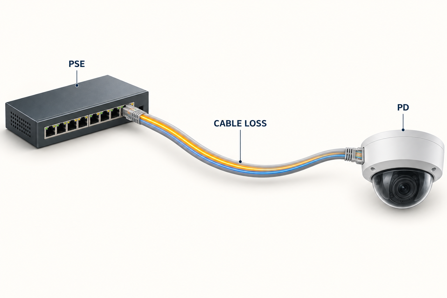
Why the 28 W camera requires a closer look
If 28 W is the required power at the camera input, a Type 2 source's 30 W label does not establish enough power at the PD interface. Its corresponding maximum PD-side figure in the table is 25.5 W. Obtain the camera's declared powering requirement and supported operating modes before selecting the switch.
This is more than a numerical rounding issue. Some endpoints start in a restricted mode, reduce radio capability or disable an accessory when the offered power is insufficient. Others do not start. A link light or a basic web interface is therefore not an acceptance test for full functionality.
Write down which functions the installation actually requires: illuminator, heater, accessory output, all radios, USB accessory or other supported load. Test that combination with the specified source. A sample that passes with its optional features disabled may not represent the delivered application.
There is also a labeling question to resolve. A device datasheet may give typical consumption, maximum input, an adapter rating and a PoE class in different places. Ask the device manufacturer which requirement governs the intended PoE operating mode. Comparing whichever two numbers happen to be largest is no more reliable than comparing the smallest ones.
Port capability and total budget are separate limits
Consider an illustrative eight-port switch supporting up to 30 W allocation on each relevant port but offering 120 W aggregate PoE capacity. The port description describes what one port can support under the stated conditions. It does not promise that eight simultaneous 30 W allocations will be available.
Eight such reservations total 240 W. Four total 120 W. Actual device power can be lower than the reservation, and equipment may use different allocation methods, but a buyer must establish the method before relying on spare measured watts. Cisco's configuration guidance illustrates why allocation and observed consumption need to be distinguished; its commands and behavior should not be assumed to apply to other manufacturers.
For the proposed switch, request the available budget with the actual power supply, input voltage and temperature. Check whether high-power operation is available on all access ports or a defined subset. The expansion plan should identify both a free compatible port and enough available allocation. One without the other is not a usable expansion position.
A procurement comparison with three endpoints
Suppose a project contains six fixed cameras, one access point and one specialist device. The cameras' maximum input is 12 W each, the AP's is 22 W and the specialist device's is 45 W. Their combined input demand is 139 W. That sum is a starting point, not the required switch output rating.
The purchasing worksheet still needs the declared class of each endpoint, cable conditions, source-side allocation and any approved operating restrictions. It may turn out that the AP uses a different reservation from its measured load, or that only certain ports support the specialist device. Neither question can be answered by the 139 W total.
| Item to resolve | Why it can change the order |
|---|---|
| Exact endpoint class and required functions | Determines the required port capability |
| Which physical ports provide that capability | Determines the usable port assignment |
| Aggregate capacity under the chosen supply arrangement | Determines whether all endpoints can operate together |
| Allocation and priority behavior | Determines admission and load-shedding behavior |
| Planned additional endpoints | Determines justified reserve, rather than an arbitrary oversizing factor |
Keep the final port map with the quotation. If the 45 W device must use a specific high-power port, label that connection in the cabinet drawing and configuration record. Otherwise a later tidy-up can create a fault even though none of the hardware has changed.
Passive powering belongs in a different compatibility check
“Passive PoE” often describes a fixed powering arrangement without the same standards-based detection and classification process. A matching connector does not establish matching voltage, polarity or pair assignment. Treat these as separate requirements and use the equipment manufacturer's approved powering method.
This is particularly important when replacing an older outdoor wireless radio. Its original injector may look interchangeable with a standards-based injector while implementing a different electrical arrangement. Record the exact radio revision, injector model and approved conversion method, if any. Avoid describing an unverified adapter as compatible merely because both ends are Ethernet connectors.
Where the supplier proposes a converter, evaluate that converter as part of the delivered system. Its input requirement, output capability, environmental rating and support responsibility need to be clear. The lowest-priced switch by itself may not remain the lowest-cost compliant system once the necessary accessories are included.
Cable quality still matters after the classes match
Standards compatibility assumes an appropriate cabling channel. Include the actual patch leads and connectors in the review, especially in cabinets with multiple transitions. Resistance and resistance unbalance can affect powering, while other cable defects affect data transmission. A simple continuity check does not cover the complete installation.
For higher-power or difficult installations, specify the required cable test and retain the report with the endpoint assignment. Fluke Networks describes PoE-oriented testing of resistance and unbalance. Use the correct test limits for the installation rather than copying a resistance threshold from an unrelated example.
A short-cable bench test remains useful for validating the equipment combination. It should be followed by a test over the installed channel at the relevant load. The two tests answer different questions: whether the devices work together, and whether the completed installation supports that combination.
Write an inquiry that can be answered precisely
For the selected TODAHIKA industrial PoE switch, ask the supplier to return a marked-up port schedule showing the supported IEEE type and classes, aggregate budget and approved input supply. Include the endpoint models, required features, cable lengths and cabinet conditions with the inquiry.
Then request the expected behavior after a cold start and after the loss of one supply where redundancy is part of the design. Confirm whether the remaining supply carries the full essential load or whether defined shedding is expected. A supply arrangement should be described by its behavior, not simply by the number of terminals visible on the enclosure.
Require the written confirmation to reference the complete ordering code and applicable hardware or firmware revision. An answer about a family of products is too broad if the family includes different PoE capabilities. Put approved alternatives in the same comparison sheet so a substitution cannot silently change the electrical design.
Acceptance should exercise the functions being purchased
At the sample stage, connect the planned device mix and confirm full required operation. Record the admitted class or allocation where the equipment exposes it, enable the relevant high-demand features and verify that all specified endpoints can start together. Monitor device uptime as well as the switch's status page.
Repeat the required case on the actual cable arrangement, then save the power supply identification and configuration. If adding another endpoint is an acceptance requirement, perform that addition with the existing load present. A screenshot of low consumption on an otherwise empty switch does not demonstrate future capacity.
The resulting evidence should answer a simple question for the next buyer: what exact combination was accepted, under which conditions, and what would require a new test? That is a more useful specification than a large wattage number detached from its port, device and power-supply boundaries.
Post time: Sep-08-2026


