
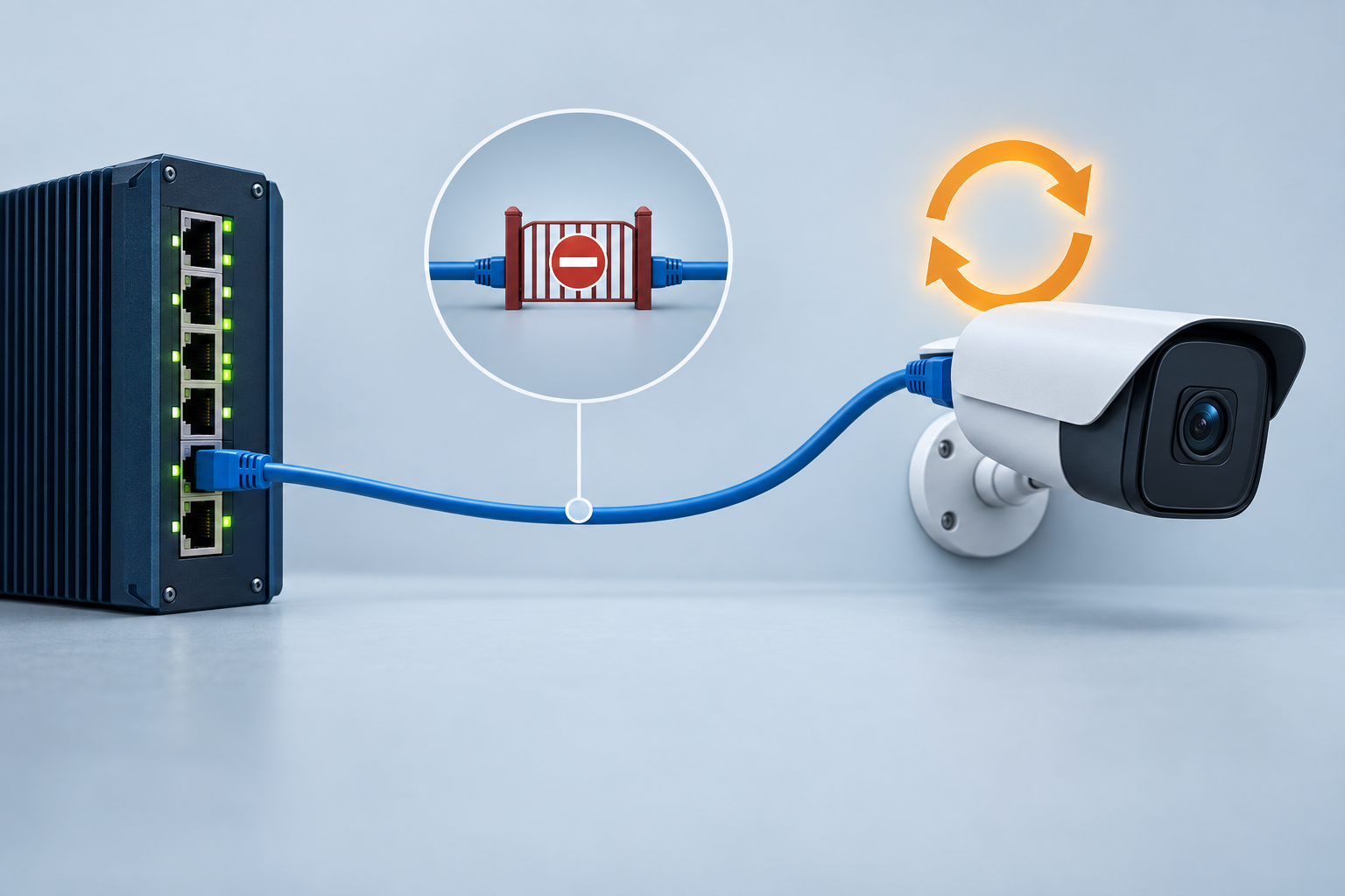
The camera starts, appears briefly in the recorder, then disappears again. A few minutes later the sequence repeats. Replacing the patch cable changes nothing. Before condemning the camera, check whether the switch is deliberately removing its power.
A PoE watchdog typically watches a configured condition and triggers a recovery action when that condition fails. Depending on the product, this may involve a reachability probe and a power cycle. If the condition is misconfigured, blocked or evaluated before startup has finished, the recovery function can create a repeating outage.
The immediate task is to establish who initiated the restart. The longer-term task is to make the recovery rule correspond to an actual service failure. A reachable IP address, a healthy video stream and a stable powered device are related, but they are not the same observation.
Preserve the event sequence before changing the timer
Collect the switch's available PoE events, device uptime, recorder events and the watchdog configuration. Confirm that their clocks are sufficiently aligned to compare the sequence. A camera disappearing first and a watchdog restart occurring later suggests a different chain of events from the switch cutting power while the camera was otherwise operating.
Look for a repeated interval. If the outage rhythm matches the configured probe interval, failed-probe threshold and restart behavior, that is a useful lead. It remains a lead until the logs or a controlled test connect the power removal to the watchdog action.
Where operationally acceptable, temporarily disable automatic recovery for the affected test port while retaining ordinary PoE power. Observe whether the camera stays up. Make the change through the approved maintenance process, document it and restore a reviewed setting after diagnosis. A stable device during this test points toward the trigger logic; it does not prove that the broader network is healthy.
Read the settings as a sequence, not as isolated numbers
Product implementations differ. For example, Moxa's managed-switch manual documents a PoE device-failure check with a target IP, check period, failed-response count and action. That example explains the kinds of settings to inspect; it does not establish the settings or capabilities of a TODAHIKA model.
For the actual switch, map the sequence from power-on to normal monitoring. Identify any startup delay, the probe mechanism, the number of failures required, the power-off duration and the restart waiting period. Ask what happens after repeated unsuccessful recoveries. Some implementations expose more control than others.
| Setting or behavior | Question to answer | Failure it can create |
|---|---|---|
| Target address | Is this the endpoint's current, intended address? | A healthy device is restarted because an old address is monitored |
| Probe source and path | Can the switch's own probe reach the target? | A technician's successful ping hides a switch-side VLAN or routing problem |
| Startup allowance | When does failure counting begin after power returns? | The camera is reset before it finishes booting |
| Failure threshold | What event duration should trigger action? | A brief network interruption causes unnecessary recovery |
| Retry policy | Does recovery stop or escalate after repeated failure? | The system loops indefinitely and destroys useful evidence |
Test the probe from the correct place
A laptop pinging the camera successfully does not prove that the watchdog can reach it. The laptop may be in the camera VLAN while the switch's management interface is elsewhere. An access rule may allow the laptop but block the switch. The target may also respond differently to the particular check the switch uses.
Check the actual source interface and supported probe behavior in the switch documentation. Verify the target address, subnet, VLAN membership, routing and relevant access rules. If the camera obtained a new address through DHCP, a fixed watchdog target may now refer to another device or nothing at all.
Do not solve this by broadly disabling segmentation or opening unnecessary access. Establish the specific communication required by the approved recovery function. If the function cannot operate across the intended management design, choose a supported monitoring arrangement rather than weakening the entire network around it.
A packet capture can help when the interface does not expose enough detail. Use an approved observation point and check whether probes leave, whether replies return and whether the return path reaches the switch. Capture only the traffic needed for the diagnosis and retain timestamps that can be compared with the power events.
Work through a startup-timing example
Suppose a camera takes 110 seconds after power restoration to become responsive in its accepted operating configuration. Imagine a watchdog starts counting failures after 30 seconds, probes every 10 seconds and acts after three failures. If the first counted probes occur at 30, 40 and 50 seconds, the watchdog can restart the camera long before it reaches the observed 110-second readiness point.
Those figures illustrate a timing conflict; they are not recommended settings. The actual first-probe timing and threshold semantics depend on the switch. Measure the camera's startup behavior with the required accessories, firmware and network services, then configure the supported allowance accordingly.
Test more than a quick warm restart. A cold start, storage check or simultaneous restart of upstream services can take longer. Keep the accepted startup envelope in the record. If a firmware change materially alters that envelope, include watchdog behavior in the update test rather than treating the old timer as permanently correct.
Separate a camera fault from a path fault
Several different failures can produce a missing reply. The camera may have hung, its cable may be disconnected, a VLAN may have changed, or an upstream path may have failed. Restarting the camera can help only some of those cases.
One useful comparison is the scope of the event. If every camera behind the same uplink fails at almost the same time, a shared path or power issue deserves attention. If one camera repeatedly loses uptime while neighboring devices stay stable, investigate that endpoint and its port. These patterns guide the next test; they are not conclusive on their own.
Avoid enabling identical aggressive recovery rules across a large camera group without a pilot. A shared network interruption could make many switches power-cycle otherwise functioning endpoints together. The subsequent startup traffic and loss of recorded coverage can extend the original disruption.
A ping response does not certify video service
The opposite problem is a camera that responds to the watchdog while its stream is unusable. Basic reachability can remain healthy while a recording session, encoder process or application path has failed. Raising the number of ping checks does not turn that probe into a video-health test.
Define what the site needs to detect. If the requirement concerns recording continuity, use the recorder or a suitable application monitor to observe that service. The switch's recovery function may remain useful, but its role should be stated accurately. Do not advertise a basic reachability watchdog as proof of end-to-end video recovery.
When evaluating an industrial PoE switch, ask which exact models and firmware versions support automatic recovery, what they monitor and which settings are available. A family-level phrase such as “PoE watchdog” is insufficient to design the fault policy.
Add a stopping point to automatic recovery
An unattended recovery system should leave evidence when it cannot restore service. Where supported, use an appropriate retry limit, increasing delay or alarm escalation. If the switch lacks those controls, address that limitation in the wider monitoring design instead of assuming that endless power cycling is acceptable.
Retain the reason for each action, the affected port and the time of power removal and restoration where available. Repeated unsuccessful recovery is useful maintenance information. It can identify a persistent cabling fault, an unreachable target or a device requiring attention.
Use local operational requirements to choose the balance between recovery speed and unnecessary resets. A remote camera with no nearby technician may justify a different response from an endpoint in a continuously staffed facility. The chosen policy should be explainable in terms of service availability and evidence, not merely a desire to use the shortest timer the menu allows.
Verify the rule with faults that have different causes
For acceptance, exercise at least the relevant supported cases: a device that is slow to start, a genuine endpoint failure, a temporary path interruption and an incorrect or unavailable target. Perform these in an isolated or approved maintenance setup. Record whether the expected event was detected, whether power was cycled and whether useful service returned.
Also verify the healthy case for a sufficient observation period. A recovery rule that reacts correctly to a forced fault but restarts healthy equipment during ordinary traffic is not ready for deployment. Compare the recorder's continuity and endpoint uptime with the switch's event history.
The final handover should contain the target address, probe path, timing rationale, recovery limits and escalation destination. When the next repeated outage occurs, that record allows the operator to distinguish an attempted repair from the fault itself—and to change the correct part of the system.
Post time: Sep-18-2026


