
A packet capture shows gaps, retransmissions or missing replies. That may explain the application fault—but first check whether the observation system lost the packets itself.
Port mirroring copies selected traffic to a monitoring destination. The source traffic and the copy do not necessarily face the same queue, bandwidth limit or capture-host resources. A missing packet in the file can therefore mean either that it was absent at the observation point or that the monitoring path failed to retain it.
The most useful capture plan begins with one question, a defined observation point and the smallest traffic set that can answer it.
State the question before choosing the source ports
For a DHCP problem, the question may be whether requests and replies cross a particular boundary. For a video interruption, it may be whether the stream is present before and after an uplink. For a VLAN issue, it may concern the tags visible at a defined stage of forwarding.
Each question suggests a different source and direction. Mirroring every port in both directions can produce a large file while making the evidence harder to interpret. It can also overload the destination and introduce duplicate observations of the same forwarded traffic.
Write down which interfaces are selected, whether ingress, egress or both are copied, and where in processing the platform creates those copies. Consult the exact switch documentation because tagging, filtering and error-frame behavior can differ.
Count the traffic copied toward the destination
Suppose one full-duplex 1 Gb/s source interface is observed in both directions. In the theoretical line-rate case, the two directions together can offer up to 2 Gb/s of traffic to the monitoring function. A single 1 Gb/s destination cannot carry that total simultaneously.
For a more modest illustrative case, three selected sources each contribute 300 Mb/s of mirrored traffic. Their sum is 900 Mb/s before considering the measurement boundaries and any other selected copies. A short burst or another mirrored source can consume the remaining capacity. The number of source ports alone does not describe the demand.
Cisco's SPAN documentation explicitly describes packets being forwarded normally while their monitoring copies are dropped at an oversubscribed destination. Confirm the relevant limits and behavior of the installed platform instead of treating a mirror as a lossless recorder.
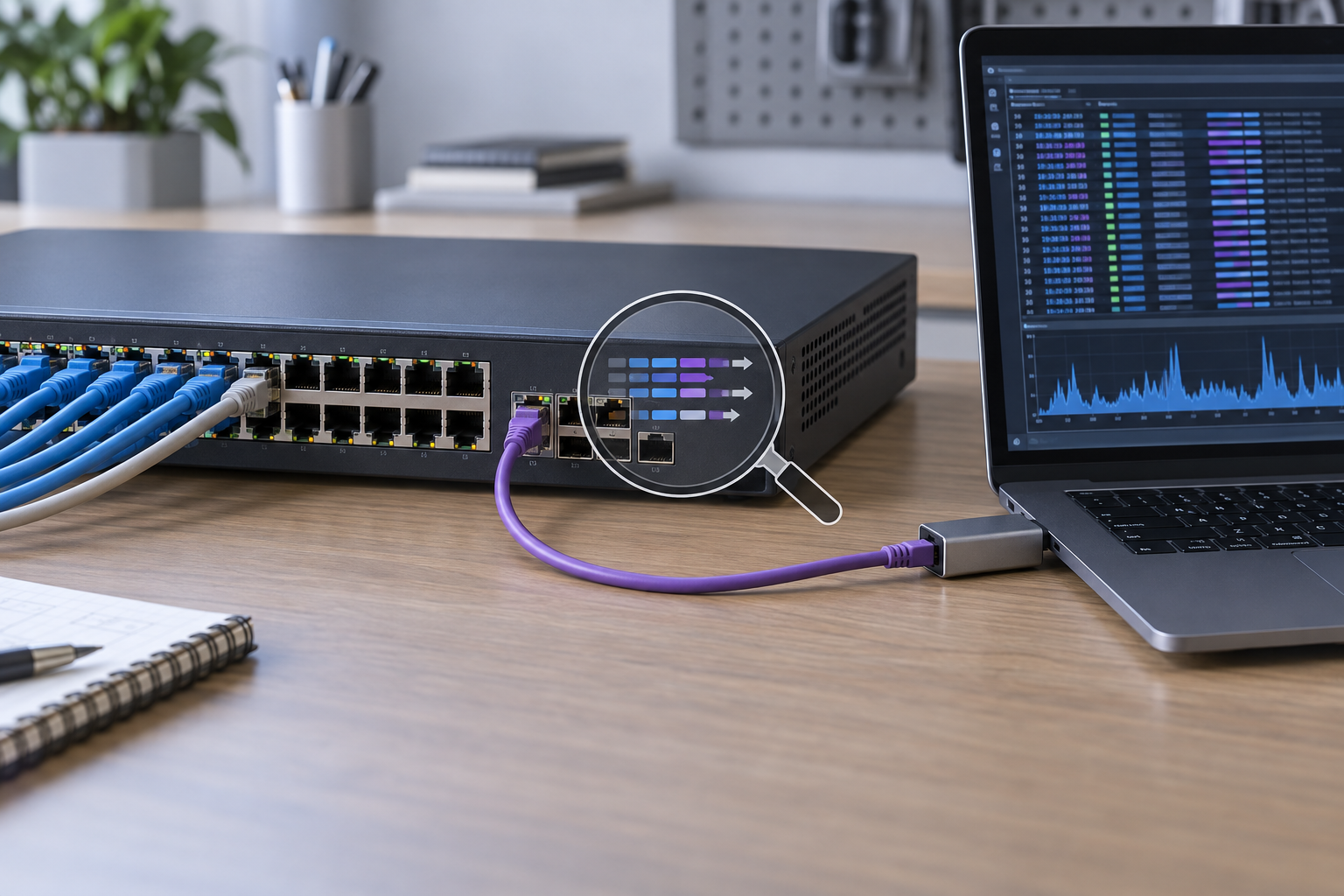
The laptop is another possible bottleneck
Check the capture interface, adapter, host processing and storage path. A suitable switch destination does not ensure that the receiving computer can retain the offered packet rate. Small packets can create a high packet-processing load even when the bit rate looks moderate.
Use the capture tool's available dropped-packet and buffer information, and review operating-system or adapter counters where appropriate. Record those observations with the capture. A file without any note about capture loss can be overinterpreted later.
Distinguish capture filtering from display filtering. A capture filter can reduce what is collected; a display filter changes what is shown after collection. Choose filters that preserve the evidence needed for the question, including relevant control traffic and both sides of the exchange.
Know whether the observation changes the frame
Some mirror modes preserve VLAN tags, while others alter or omit information according to the platform and configuration. Encapsulated remote mirroring introduces another transport and its own capacity and MTU considerations. Verify what the monitoring destination should receive before using the file to prove an on-wire tagging claim.
If both ingress and egress points are selected, the same logical packet may appear more than once. Timing and modifications can help explain the copies, but duplicate-looking packets should not automatically be labeled a production loop or retransmission.
Likewise, a switch may not mirror every malformed or internally dropped frame. Absence from the capture does not prove that the physical interface never received an error. Correlate the file with interface counters and the documentation for the chosen observation point.
A capture worksheet prevents ambiguous evidence
| Item | Record before the test |
|---|---|
| Diagnostic question | The specific missing or incorrect behavior being investigated |
| Observation point | Switch, source interface or VLAN, and direction |
| Mirror behavior | Relevant tagging, filtering and platform restrictions |
| Capacity | Estimated copied rate, destination speed and capture-host capability |
| Timing | Clock relationship between capture, switch logs and application events |
| Test trigger | The repeatable action or event that should appear in the capture |
| Evidence limits | Any dropped copies, capture-host losses or unobserved path segments |
Include configuration changes made for the capture and the plan to remove temporary monitoring afterward. The destination may have a special port role while mirroring is active; do not assume it behaves like an ordinary production access port.
Compare two observation points when the question requires it
If the purpose is to locate loss along a path, one capture can be insufficient. A carefully correlated observation before and after a suspected boundary can show whether the same required traffic reaches both points. Keep the capture setup and timestamps suitable for that comparison.
Do not assume that two unsynchronized laptops provide precise transit timing. Their clock relationship and capture behavior can dominate a small apparent delay. Use an appropriate measurement method when the requirement concerns latency rather than simply the presence of a transaction.
For an intermittent problem, preserve the surrounding control exchanges and application event. A tiny excerpt containing only the final missing reply can omit the address change, session reset or topology event that explains it.
Treat captured payloads as project data
Capture only what the approved troubleshooting task requires, and store it under the site's access and retention rules. Packet files can contain application content, identifiers or credentials depending on the protocols in use. Keep sharing and retention limited to the intended diagnostic purpose.
Where a supplier needs evidence, agree which fields or excerpts are necessary and how they should be transferred. A concise event description, topology and relevant counters can often help interpret the capture without sending unrelated traffic.
This is part of making the evidence usable: the team should know where the file came from, what it contains, who may access it and what conclusions it can support.
Specify diagnostic capability before choosing the switch
For a TODAHIKA managed-switch inquiry, describe the expected observation tasks. Ask which source types and directions are supported, how many sessions are available, what destination speeds can be used and which limitations apply to the exact model and firmware.
Validate the feature during commissioning with known test traffic. Confirm that the expected exchange appears and that the collection path is not dropping at the required workload. Retain the configuration and evidence limits with the test result.
A good packet capture is a documented observation, not a complete view of the network by default. Establishing how the file was collected is what makes its missing packets—and its visible ones—useful evidence.
Post time: Oct-23-2026


