
You are quoting a project to connect a remote water treatment plant four kilometers from headquarters. A quick online search turns up dozens of low-cost Customer Premises Equipment (CPE) devices with “10-Kilometer Long-Distance Transmission!” stamped on the packaging.
You purchase a pair, mount them to poles, align the antennas, and power on the link.
Instead of a stable high-definition video stream, you get a choppy, dropping connection struggling to reach 2 Mbps. Technical support gives you the standard answer: “10 km is the theoretical maximum in ideal conditions.”
In the B2B networking industry, “theoretical range” is one of the most misused marketing metrics.
As a global manufacturer of Wireless CPE and Point-to-Point (PtP) bridges for security integrators and Wireless Internet Service Providers (WISPs), Todahika rejects inflated performance claims. Here is the engineering reality behind wireless range and how to calculate actual usable bandwidth over long distances.
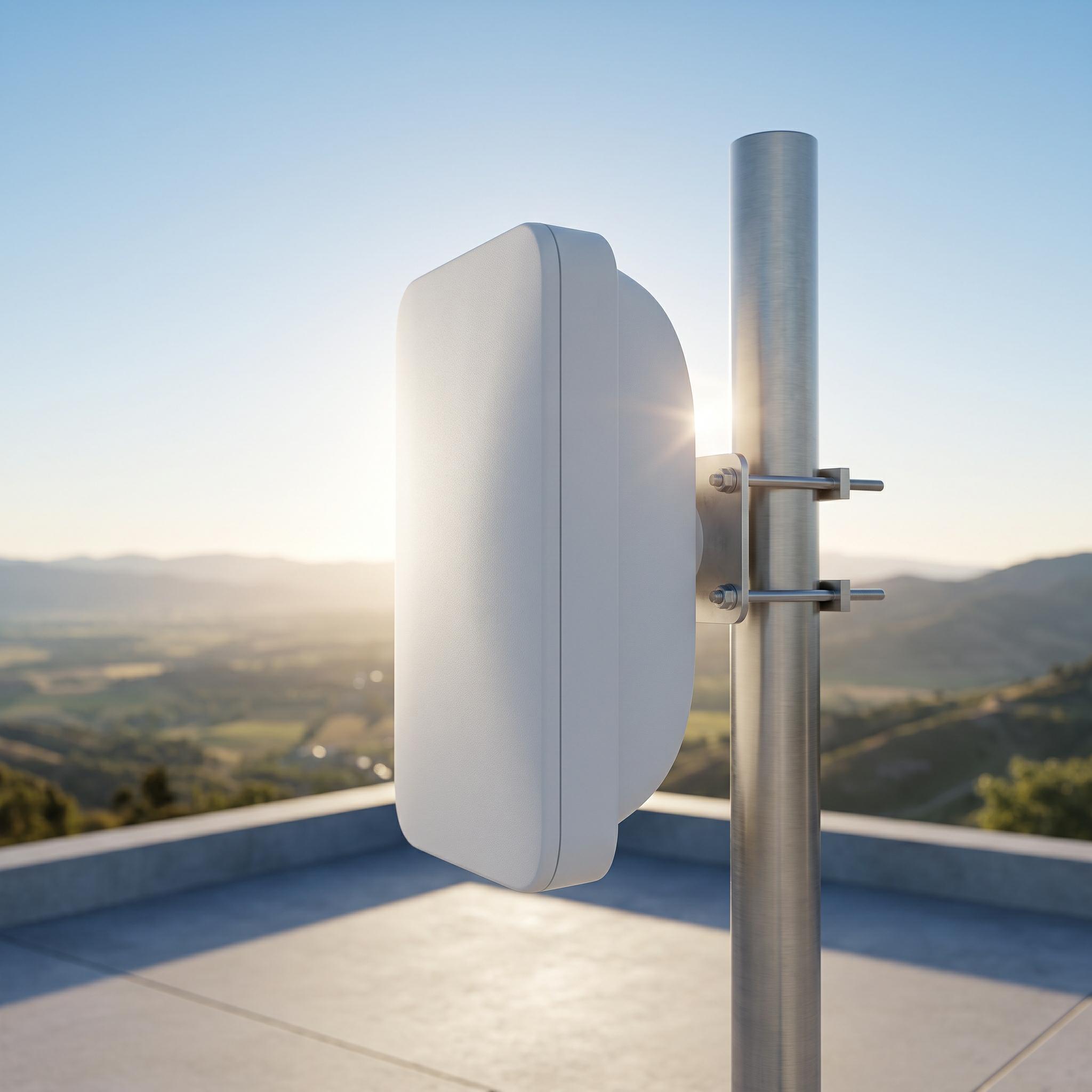
How Manufacturers Inflate 10 km Range Claims
When a manufacturer claims a wireless bridge reaches 10 kilometers, the figure comes from lab testing that does not reflect real-world operational environments.
To achieve a “10 km” rating in test environments, manufacturers rely on three unrealistic conditions:
-
Zero-Noise Environments: Testing takes place over salt flats, deserts, or open ocean water with zero competing 5 GHz Wi-Fi signals, cellular towers, or electromagnetic interference.
-
Minimum Modulation (MCS0): Protocol modulation is reduced to the lowest setting. This maintains a basic link capable of passing ping packets at 10 km, but usable throughput drops below 1 Mbps.
-
Zero Fade Margin: Distance is calculated at exact receiver sensitivity limits (-96 dBm) with zero margin for rain, fog, or humidity.
Attempting to run multiple 4K CCTV streams across this type of link in a suburban environment results in an immediate connection failure.
Three Real-World Blockers of Long-Distance Wireless Transmission
Delivering reliable high-throughput data across long distances requires overcoming three physical constraints:
1. The Fresnel Zone
Wireless signals do not travel in a razor-thin laser beam. RF energy diffuses into an elliptical shape between two antennas known as the Fresnel zone.
If trees, rooftops, or passing vehicles obstruct more than 20% of this 3D region, signal diffraction and phase cancellation occur. Even with a clear visual line of sight (LOS), link throughput can drop by up to 80%.
2. The Real-World Noise Floor
Clean testing environments feature an ambient radio noise floor of approximately -100 dBm. In industrial parks or suburban areas, heavy deployment of Wi-Fi routers, Bluetooth devices, and power lines raises the ambient noise floor to roughly -85 dBm.
This 15 dB difference significantly reduces the Signal-to-Noise Ratio (SNR). Maintaining high-order modulation (such as 256-QAM or 1024-QAM in Wi-Fi 6) requires a high SNR. Without a high-gain dish antenna, achieving long-distance transmission in dense RF environments is mathematically unfeasible.
3. Atmospheric Humidity and Rain Fade
Water molecules absorb 5 GHz and 6 GHz radio frequencies. A 5 km link yielding 300 Mbps on a clear day will experience heavy attenuation during downpours. Without a 15 dB to 20 dB fade margin built into the link budget, rainfall will drop the network offline.
The Todahika Engineering Approach: Honest Link Planning
Todahika designs CPE and PtP bridges to deliver predictable, verified field performance.
We provide installers with transparent link planning tools and hardware capabilities:
-
Realistic Bandwidth Ratings: Todahika specifications publish real-world throughput charts. A “5 km Recommended Distance” rating guarantees over 100 Mbps of usable throughput under actual field conditions—not just basic ping packets.
-
Integrated Spectrum Analysis: Our firmware includes a visual web GUI spectrum analyzer, allowing installers to scan the local 5 GHz band and identify clean, unassigned channels prior to deployment.
-
Pre-Paired DIP Switch Kits: For 1 km to 3 km deployments, our plug-and-play bridge kits feature physical DIP switches. Setting units to Master and Slave connects the link automatically within two minutes without software configuration.
-
High-Gain Integrated Antennas: We integrate high-efficiency MIMO directional panel and dish antennas with narrow beamwidths to concentrate RF energy and reject side-lobe interference from adjacent structures.
Stop Buying Inflated Specifications
Never base hardware purchasing decisions solely on maximum packaging claims. Reliable long-range backhaul requires proper link budget calculations and realistic performance data.
Planning a complex wireless link?
Send your site plan and GPS coordinates to the Todahika engineering team. We will analyze line-of-sight clearance, calculate link budgets, and recommend the exact CPE and antenna configuration required for your target bandwidth.
Post time: Jul-20-2026


